For lab this week, we focus on both on sensing, to bring in new modes of input into your devices, as well as prototyping the physical look and feel of the device. You will think about the physical form the device needs to perform the sensing as well as present the display or feedback about what was sensed.
As always, pull updates from the class Interactive-Lab-Hub to both your Pi and your own GitHub repo. As we discussed in the class, there are 2 ways you can do so:
**[recommended]**Option 1: On the Pi, cd to your Interactive-Lab-Hub, pull the updates from upstream (class lab-hub) and push the updates back to your own GitHub repo. You will need the personal access token for this.
pi@ixe00:~$ cd Interactive-Lab-Hub
pi@ixe00:~/Interactive-Lab-Hub $ git pull upstream Fall2021
pi@ixe00:~/Interactive-Lab-Hub $ git add .
pi@ixe00:~/Interactive-Lab-Hub $ git commit -m "get lab4 content"
pi@ixe00:~/Interactive-Lab-Hub $ git push
Option 2: On your your own GitHub repo, create pull request to get updates from the class Interactive-Lab-Hub. After you have latest updates online, go on your Pi, cd to your Interactive-Lab-Hub and use git pull to get updates from your own GitHub repo.
- What do prototypes prototype?
- Paper prototyping is used by UX designers to quickly develop interface ideas and run them by people before any programming occurs.
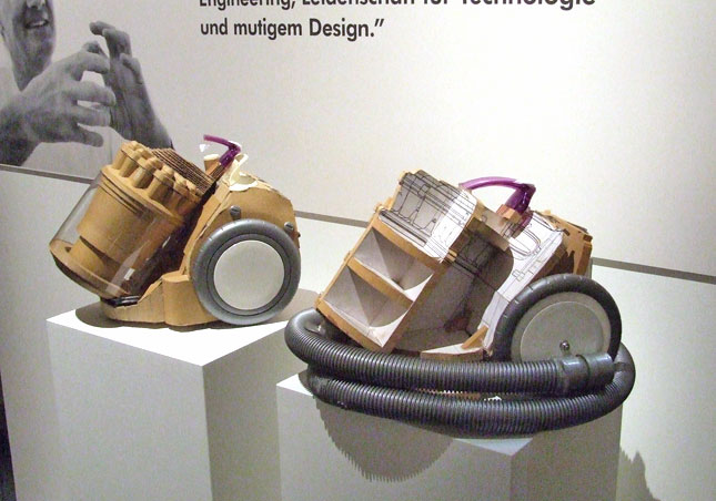
- Cardboard prototypes help interactive product designers to work through additional issues, like how big something should be, how it could be carried, where it would sit.
- Tips to Cut, Fold, Mold and Papier-Mache Cardboard from Make Magazine.
- Surprisingly complicated forms can be built with paper, cardstock or cardboard. The most advanced and challenging prototypes to prototype with paper are cardboard mechanisms which move and change.
- Dyson Vacuum Cardboard Prototypes
- Cardboard (start collecting those shipping boxes!)
- Found objects and materials--like bananas and twigs.
- Cutting board
- Cutting tools
- Markers
(We do offer shared cutting board, cutting tools, and markers on the class cart during the lab, so do not worry if you don't have them!)
The deliverables for this lab are, writings, sketches, photos, and videos that show what your prototype:
- "Looks like": shows how the device should look, feel, sit, weigh, etc.
- "Works like": shows what the device can do.
- "Acts like": shows how a person would interact with the device.
For submission, the readme.md page for this lab should be edited to include the work you have done:
- Upload any materials that explain what you did, into your lab 4 repository, and link them in your lab 4 readme.md.
- Link your Lab 4 readme.md in your main Interactive-Lab-Hub readme.md.
- Group members can turn in one repository, but make sure your Hub readme.md links to the shared repository.
- Labs are due on Mondays, make sure to submit your Lab 4 readme.md to Canvas.
B) OLED screen
D) Materiality
We want to introduce you to the capacitive sensor in your kit. It's one of the most flexible input devices we are able to provide. At boot, it measures the capacitance on each of the 12 contacts. Whenever that capacitance changes, it considers it a user touch. You can attach any conductive material. In your kit, you have copper tape that will work well, but don't limit yourself! In the example below, we use Twizzlers--you should pick your own objects.


Plug in the capacitive sensor board with the QWIIC connector. Connect your Twizzlers with either the copper tape or the alligator clips (the clips work better). In this lab, we will continue to use the circuitpython virtual environment we created before. Activate circuitpython and cd to your Lab 4 folder to install the requirements by:
(circuitpython) pi@ixe00:~/Interactive-Lab-Hub/Lab 4 $ pip3 install -r requirements.txt

(circuitpython) pi@ixe00:~/Interactive-Lab-Hub/Lab 4 $ python cap_test.py
Twizzler 10 touched!
Twizzler 6 touched!
We here want you to get to know this awesome sensor Adafruit APDS-9960. It is capable of sensing proximity, light (also RGB), and gesture!

Connect it to your pi with Qwiic connector and try running the three example scripts individually to see what the sensor is capable of doing!
(circuitpython) pi@ixe00:~/Interactive-Lab-Hub/Lab 4 $ python proximity_test.py
...
(circuitpython) pi@ixe00:~/Interactive-Lab-Hub/Lab 4 $ python gesture_test.py
...
(circuitpython) pi@ixe00:~/Interactive-Lab-Hub/Lab 4 $ python color_test.py
...
You can go the the Adafruit GitHub Page to see more examples for this sensor!
A rotary encoder is an electro-mechanical device that converts the angular position to analog or digital output signals. The Adafruit rotary encoder we ordered for you came with separated breakout board and encoder itself, that is, they will need to be soldered if you have not yet done so! We will be bringing the soldering station to the lab class for you to use, also, you can go to the MakerLAB to do the soldering off-class. Here is some guidance on soldering from Adafruit. When you first solder, get someone who has done it before (ideally in the MakerLAB environment). It is a good idea to review this material beforehand so you know what to look at.


Connect it to your pi with Qwiic connector and try running the example script, it comes with an additional button which might be useful for your design!
(circuitpython) pi@ixe00:~/Interactive-Lab-Hub/Lab 4 $ python encoder_test.py
You can go to the Adafruit Learn Page to learn more about the sensor! The sensor actually comes with an LED (neo pixel): Can you try lighting it up?
A joystick can be used to sense and report the input of the stick for it pivoting angle or direction. It also comes with a button input!
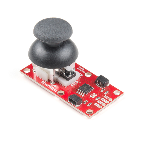
Connect it to your pi with Qwiic connector and try running the example script to see what it can do!
(circuitpython) pi@ixe00:~/Interactive-Lab-Hub/Lab 4 $ python joystick_test.py
You can go to the SparkFun GitHub Page to learn more about the sensor!
Note: We did not distribute this sensor to you, so if you are interested in playing with it, please come pick it up from the TA!
Earlier we have asked you to play with the proximity sensor, which is able to sense object within a short distance. Here, we offer Qwiic Multi Distance Sensor, which has a field of view of about 25° and is able to detect objects up to 3 meters away!
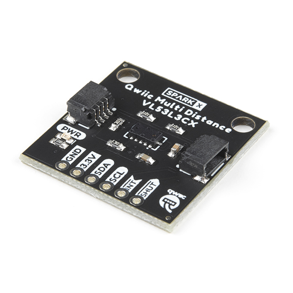
Connect it to your pi with Qwiic connector and try running the example script to see how it works!
(circuitpython) pi@ixe00:~/Interactive-Lab-Hub/Lab 4 $ python distance_test.py
You can go to the SparkFun GitHub Page to learn more about the sensor and see other examples!
Usually, sensors need to positioned in specific locations or orientations to make them useful for their application. Now that you've tried a bunch of the sensors, pick one that you would like to use, and an application where you use the output of that sensor for an interaction. For example, you can use a distance sensor to measure someone's height if you position it overhead and get them to stand under it.
***Draw 5 sketches of different ways you might use your sensor, and how the larger device needs to be shaped in order to make the sensor useful.***
***What are some things these sketches raise as questions? What do you need to physically prototype to understand how to anwer those questions?***
***Pick one of these designs to prototype.***
Here is an Pi with a paper faceplate on it to turn it into a display interface:

This is fine, but the mounting of the display constrains the display location and orientation a lot. Also, it really only works for applications where people can come and stand over the Pi, or where you can mount the Pi to the wall.
Here is another prototype for a paper display:

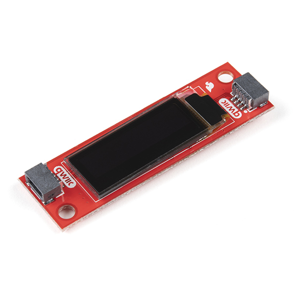
Your kit includes these SparkFun Qwiic OLED screens. These use less power than the MiniTFTs you have mounted on the GPIO pins of the Pi, but, more importantly, they can be more flexibily be mounted elsewhere on your physical interface. The way you program this display is almost identical to the way you program a Pi display. Take a look at oled_test.py and some more of the Adafruit examples.

It holds a Pi and usb power supply, and provides a front stage on which to put writing, graphics, LEDs, buttons or displays.
This design can be made by scoring a long strip of corrugated cardboard of width X, with the following measurements:
| Y height of box - thickness of cardboard |
Z depth of box - thickness of cardboard |
Y height of box | Z depth of box | H height of faceplate * * * * * (don't make this too short) * * * * * |
|---|
Fold the first flap of the strip so that it sits flush against the back of the face plate, and tape, velcro or hot glue it in place. This will make a H x X interface, with a box of Z x X footprint (which you can adapt to the things you want to put in the box) and a height Y in the back.
Here is an example:

Think about how you want to present the information about what your sensor is sensing! Design a paper display for your project that communicates the state of the Pi and a sensor. Ideally you should design it so that you can slide the Pi out to work on the circuit or programming, and then slide it back in and reattach a few wires to be back in operation.
***Sketch 5 designs for how you would physically position your display and any buttons or knobs needed to interact with it.***
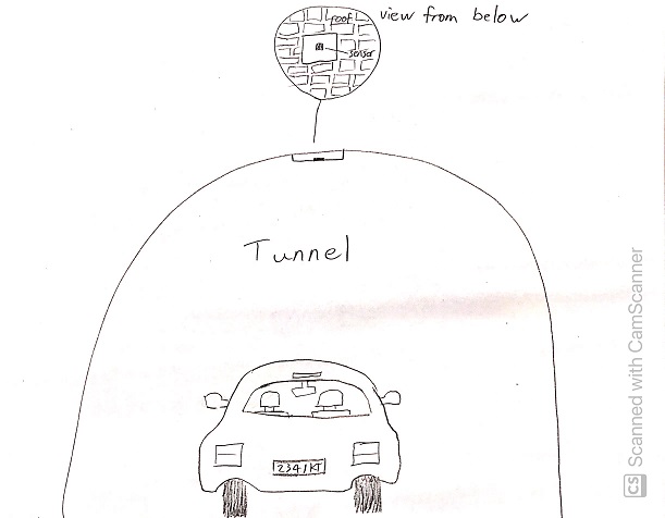
My idea is for an easily portable motion sensor that can be installed somewhere on the road in order to detect cars. It would be able to count the cars as well as potentially identifying the color of the cars for various purposes such as law enforcement.
***What are some things these sketches raise as questions? What do you need to physically prototype to understand how to anwer those questions?***
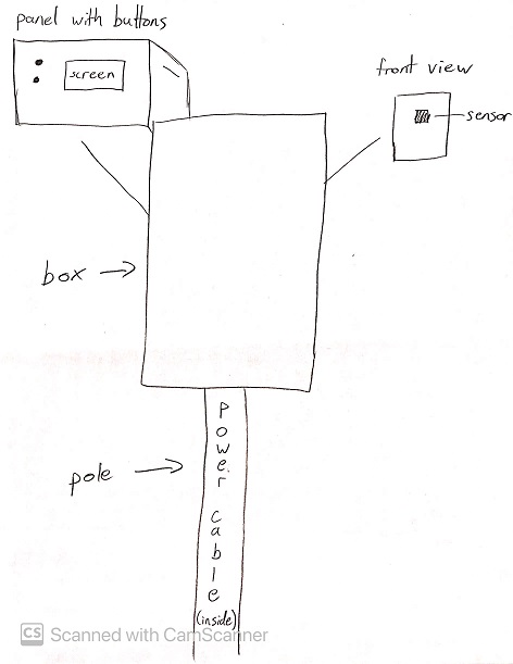
My first sketch is reminiscent of a typical speed radar. Functionally it would probably work quite well, but the installation would be a lot more permanent than I would like. The good thing about this design is that it would have a back panel that one could use to access the screen and controls for the device.
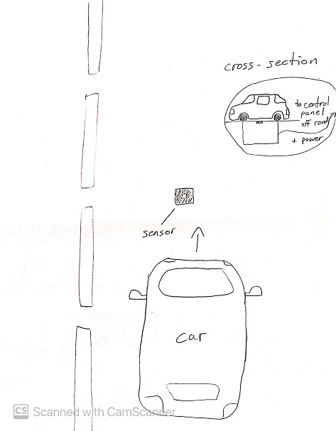
The second sketch raises the question of how to keep the sensor clean/clear when installing it into the road itself. Furthermore, it would not be an easy installation at all, and certainly not portable. It could potentially be adjusted to be installed inside of pre-existing structures in the road such as cat-eyes.
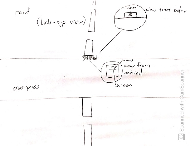
The third sketch makes me wonder what the physical limitations of the detector are. It is quite likely that some overpasses would be too far above the road for the device to work properly. The good thing about it is that it could be installed fairly easily and would provide access to the user from the overpass itself.
The fourth sketch makes me question whether the design makes the device too vulnerable to the elements and physical damage. The good thing about this device is that it is user-oriented, but it makes me wonder why someone would want to use a device like this in such a manner. Perhaps the functionality for this design could be a little different; more oriented towards home-use than roadside use.
The fifth sketch again brings into question the difficulty of installing the device. On the plus side, it could be made quite secure with this design, and depending on the tunnel, would miss fewer cars since the tunnel forces cars to follow very similar paths.
All the designs raise the question of how one would supply the device with power. It could simply use a battery pack, but the designs that incorporate poles (and look more like traditional speed radars) could be made more permanent by having an actual power cable coming up the pole. However, since the design is supposed to be portable, I am less inclined to use those designs, or at least to incorporate a power cable - using a battery pack makes more sense for this use case.
***Pick one of these display designs to integrate into your prototype.***
I chose the first (1) design for my prototype.
***Explain the rationale for the design.*** (e.g. Does it need to be a certain size or form or need to be able to be seen from a certain distance?)
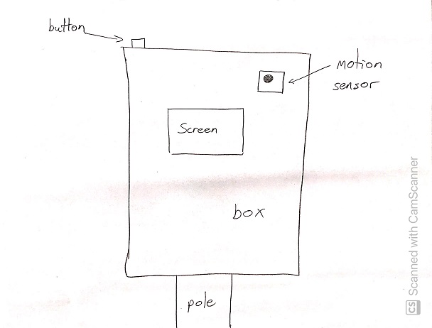
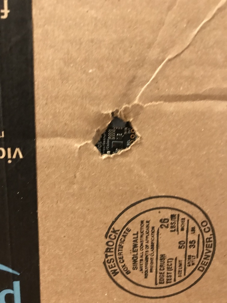
I chose the first design because it is a lot more feasible and easy to test, but also because I want to design it such that it has a screen and controls on the opposite side of the sensor (and hidden behind a panel). I want the sensor to face the road, but not any of the other parts of the device. I want it to be minimally exposed to potential physical damage, so everything but a small opening for the sensor would be hidden inside the box or behind the rear panel. The pole component of the design seems like it would get in the way, however, so for my rough prototype I will only create the box with the back panel, which is a more portable and modular design. Another reason I chose this prototype is that it could be easily adapted to suit other purposes, since additional components can be installed inside of the box.
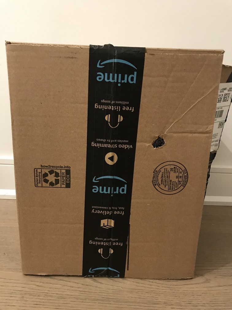
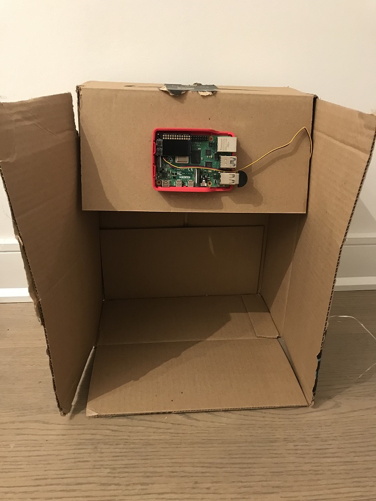
Build a cardbord prototype of your design.
***Document your rough prototype.***
Front view:
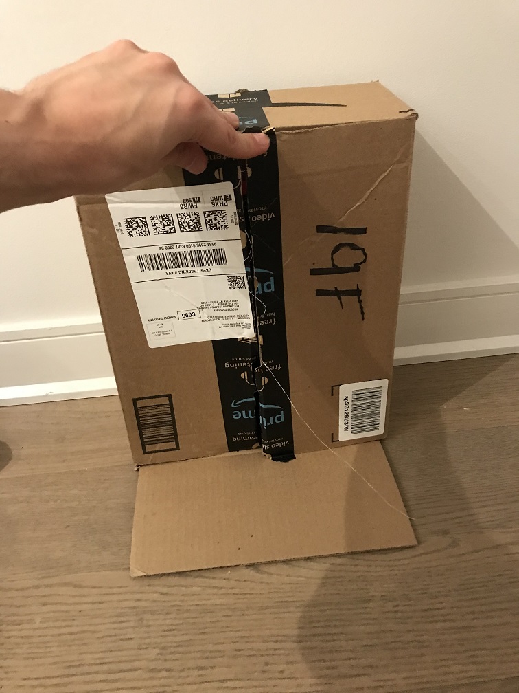
Back panel:
LAB PART 2
Following exploration and reflection from Part 1, complete the "looks like," "works like" and "acts like" prototypes for your design, reiterated below.
In the class kit, you should be able to find the Qwiic Servo Controller and Micro Servo Motor SG51. The Qwiic Servo Controller will need external power supply to drive, which we will be distributing the battery packs in the class. Connect the servo controller to the miniPiTFT through qwiic connector and connect the external battery to the 2-Pin JST port (ower port) on the servo controller. Connect your servo to channel 2 on the controller, make sure the brown is connected to GND and orange is connected to PWM.

In this exercise, we will be using the nice ServoKit library developed by Adafruit! We will continue to use the circuitpython virtual environment we created. Activate the virtual environment and make sure to install the latest required libraries by running:
(circuitpython) pi@ixe00:~/Interactive-Lab-Hub/Lab 4 $ pip3 install -r requirements.txt
A servo motor is a rotary actuator or linear actuator that allows for precise control of angular or linear position. The position of a servo motor is set by the width of an electrical pulse, that is, we can use PWM (pulse-width modulation) to set and control the servo motor position. You can read this to learn a bit more about how exactly a servo motor works.
Now that you have a basic idea of what a servo motor is, look into the script qwiic_servo_example.py we provide. In line 14, you should see that we have set up the min_pulse and max_pulse corresponding to the servo turning 0 - 180 degree. Try running the servo example code now and see what happens:
(circuitpython) pi@ixe00:~/Interactive-Lab-Hub/Lab 4 $ python servo_test.py
It is also possible to control the servo using the sensors mentioned in as in part A and part B, and/or from some of the buttons or parts included in your kit, the simplest way might be to chain Qwiic buttons to the other end of the Qwiic OLED. Like this:

You can then call whichever control you like rather than setting a fixed value for the servo. For more information on controlling Qwiic devices, Sparkfun has several python examples, such as this.
We encourage you to try using these controls, while paying particular attention to how the interaction changes depending on the position of the controls. For example, if you have your servo rotating a screen (or a piece of cardboard) from one position to another, what changes about the interaction if the control is on the same side of the screen, or the opposite side of the screen? Trying and retrying different configurations generally helps reveal what a design choice changes about the interaction -- make sure to document what you tried!
I tested the basic functionality of the servo and decided to incorporate it into my prototype.
For the second part of this lab I decided to change the functionality of the device, while still using the original form of the prototype as the base for my design. I decided that the car-counting functionality was too basic and boring, based on my own opinion as well as feedback from others. Instead, I retained the motion sensor as a trigger for the rest of the device's functionality. The design is now used for automatic doors with voice recognition. The motivation behind this is to serve people who are wheelchair-bound. They will be able to open doors using only their voice, with the added benefit of the function only triggering when near the motion sensor, which would be placed near the door itself.
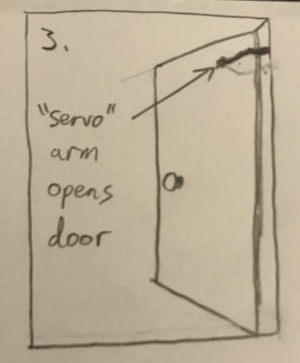
Below is a sketch of the final design for the device (not to scale).
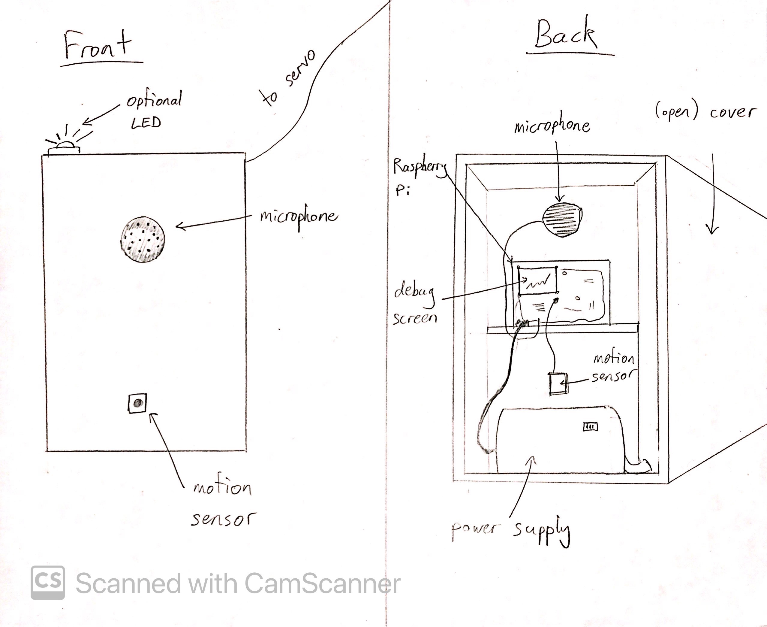
The device is composed of the following: a motion sensor, a microphone, a speaker, and a servo arm to serve as a proxy for the door itself. The functionality is as follows:
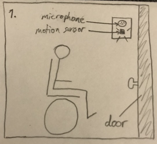
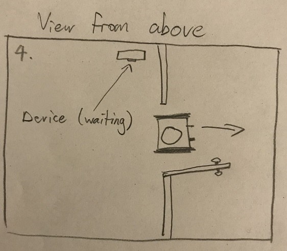
- The user must approach the motion sensor, which would be located near a door. This would trigger the Raspberry Pi to "listen" for the activation phrase.
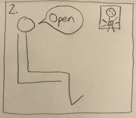
- The user must then say "open door"
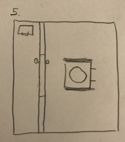
- The Raspberry Pi will then open the door (modeled by the servo in my prototype)
- The Raspberry Pi will then wait for a little while after the last movement detected by the motion detector before closing
The idea is that a wheelchair-bound person can seamlessly navigate their way, be it at home or any other building, without having to stop to press buttons or make any other physical effort besides speaking. In particular, persons who are paralyzed and require a text-to-speech device (or similar) to speak could still operate the doors, as my design would be able to register their their commands.
Below is a visual description of how the interaction would work in practice.
Functionality test video: