Visual Language Maps for Robot Navigation
Chenguang Huang, Oier Mees, Andy Zeng, Wolfram Burgard
See README of this fork for details about setting up VLMaps to work with the telepresence system
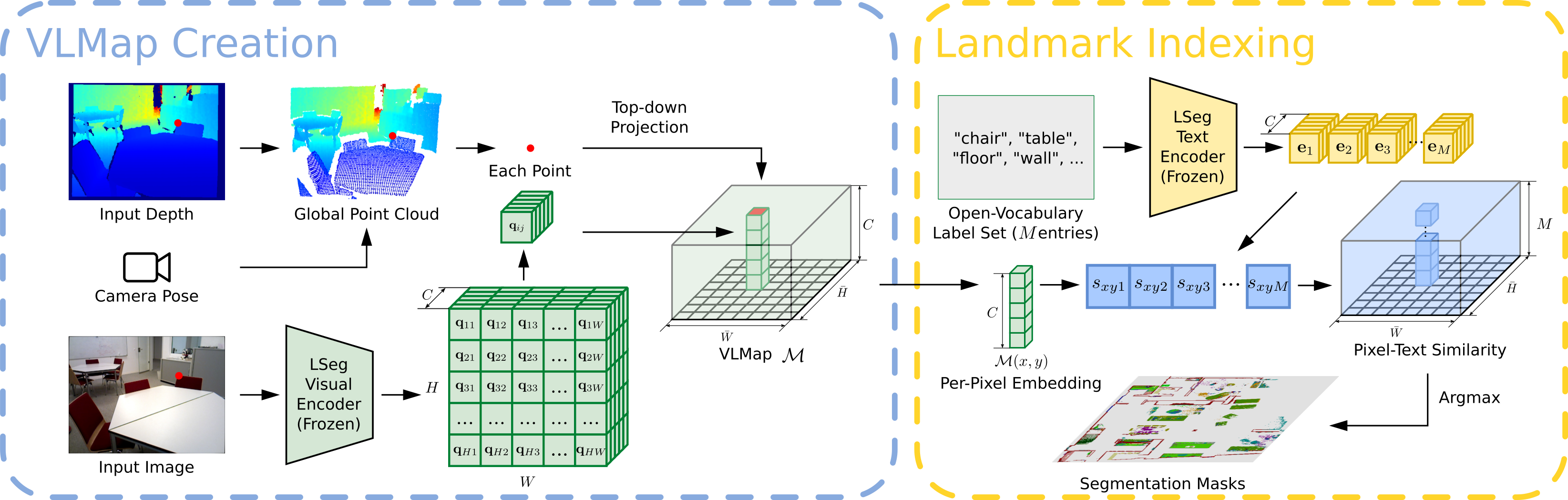
We present VLMAPs (Visual Language Maps), a spatial map representation in which pretrained visuallanguage model features are fused into a 3D reconstruction of the physical world. Spatially anchoring visual language features enables natural language indexing in the map, which can be used to, e.g., localize landmarks or spatial references with respect to landmarks – enabling zero-shot spatial goal navigation without additional data collection or model finetuning.


Try VLMaps creation and landmark indexing in
To begin on your own machine, clone this repository locally
git clone https://github.com/vlmaps/vlmaps.gitInstall requirements:
$ conda create -n vlmaps python=3.8 -y  # or use virtualenv
$ conda activate vlmaps
$ conda install jupyter -y
$ cd vlmaps
$ bash install.bashgit checkout demoStart the jupyter notebook
$ jupyter notebook demo.ipynbUse the master branch
git checkout masterTo build VLMaps for simulated environments, we manually collected 10 sequences of RGB-D videos among 10 scenes in Habitat simulator with Matterport3D dataset. We provide script and pose meta data to generate the RGB-D videos. Please follow the next few steps to generate the dataset.
Please check Dataset Download, sign the Terms of Use, and send to the responsible person to request the Matterport3D mesh for the use in Habitat simulator. The return email will attach a python script to download the data. Copy and paste the script to a file ~/download_mp.py. Run the following to download the data:
cd ~
# download the data at the current directory
python2 download_mp.py -o . --task habitat
# unzip the data
unzip v1/tasks/mp3d_habitat.zip
# the data_dir is mp3d_habitat/mp3d-
Configure the
config/generate_dataset.yaml.- Change the value for
defaults/data_pathsinconfig/generate_dataset.yamltodefault. - Change the
habitat_scene_dirandvlmaps_data_dirinconfig/data_paths/default.yamlaccording to the following steps. - Change the
habitat_scene_dirto the downloaded Matterport3D dataset~/mp3d_habitat/mp3d.# the structure of the habitat_scene_dir looks like this habitat_scene_dir |-5LpN3gDmAk7 | |-5LpN3gDmAk7.glb | |-5LpN3gDmAk7_semantic.ply | |-... |-gTV8FGcVJC9 | |-gTV8FGcVJC9.glb | |-gTV8FGcVJC9_semantic.ply | |-... |-jh4fc5c5qoQ | |-jh4fc5c5qoQ.glb | |-jh4fc5c5qoQ_semantic.ply | |-... ... - Change the
vlmaps_data_dirto downloaded dataset# the structure of the vlmaps_data_dir looks like this vlmaps_data_dir |-5LpN3gDmAk7_1 | |-poses.txt |-gTV8FGcVJC9_1 | |-poses.txt |-jh4fc5c5qoQ_1 | |-poses.txt ... - Change
data_cfg.resolution.wanddata_cfg.resolution.hto adjust the resolution of the generated rgb, depth, and semantic images. - Change
rgb,depth, andsemantictotrueto generate corresponding data, and tofalseto ignore corresponding data. - Change
camera_heightto change the height of camera relative to the robot base
# go to <REPO_ROOT>/dataset of this repository
cd dataset
# the generated dataset will be in the same
python generate_dataset.py
- Change the value for
Run the following code to collect your own data (for example for scene gTV8FGcVJC9):
python dataset/collect_custom_dataset.py scene_names=["gTV8FGcVJC9"]The generated data folder will be <scene_name>_<id> under vlmaps_data_dir in config/data_paths/default.yaml (If you already set the data_paths to default). The <scene_name> is gTV8FGcVJC9 for the above command, and the <id> depends on the existing data folders for this scene. If gTV8FGcVJC9_1 exists, then the new folder name will be gTV8FGcVJC9_2.
-
Change the value for
defaults/data_pathsinconfig/map_creation_cfg.yamltodefault. -
Change the
habitat_scene_dirandvlmaps_data_dirinconfig/data_paths/default.yamlaccording to the steps in the Generate Dataset section above. -
Run the following command to build the VLMap. The code builds a 3D map where each voxel contains the LSeg embedding.
cd application
python create_map.py

- Change the scene you want to generate VLMap for by changing
scene_id(0-9) inconfig/map_creation_cfg.yaml. If you use your customized data,scene_idindicates the id of the sorted subfolder undervlmaps_data_dirpath you set inconfig/paths/default.yaml. - Customize the map by changing the parameters in
config/params/default.yaml- Change the resolution of the map by changing
cs(cell size in meter) andgs(grid size)
- Change the resolution of the map by changing
- Customize the camera pose and base pose by changing
config/vlmaps.yaml. Change thepose_infosection.pose_typemeans the type of poses stored inposes.txtfiles. Set it tomobile_basewhen the poses are the poses for the base on the robot, and set it tocamera_basewhen the poses are the poses for the camera.rot_typemeans the format of data you save at each line of theposes.txtfile. Set it toquatif you save the pose aspx, py, pz, qx, qy, qz, qw. Set it tomatif you save the flattened (4, 4) transformation matrix at each line. By default, it is set toquat.- If you set
pose_typeasmobile_base, you should also modify the following parameters inpose_info:camera_heightmeans the camera height relative to the base. Change it if you set different camera height when you generate the dataset.base2cam_rotmeans the row-wise flattened rotation matrix from robot base to the camera coordinate frame (z forward, x right, y down).base_forward_axis,base_left_axis,base_up_axis: your robot base coordinate. They mean what is the coordinate of the forward unit vector [1, 0, 0] projected into your robot base frame, the coordinate of the left unit vector [0, 1, 0] projected into your robot base frame, the coordinate of the upward unit vector [0, 0, 1] projected into your robot base frame.
- Other settings in
config/vlmaps.yamlskip_framemeans that only whenframe_i % skip_frame == 0do we use the framecam_calib_matis the flattened camera intrinsics matrixdepth_sample_rate: we only back project randomly sampledh * w / depth_sample_ratepixels at each frame. You can change this to a higher value to increase the mapping speed at the cost of having a sparser point cloud at each frame.
-
Change the value for
defaults/data_pathsinconfig/map_indexing_cfg.yamltodefault. -
Change the
habitat_scene_dirandvlmaps_data_dirinconfig/data_paths/default.yamlaccording to the steps in the Generate Dataset section above. -
Run the following command to index a VLMap you built
cd application
python index_map.py

- Change the file
config/map_indexing_cfg.yamldecay_rate: set the heatmap decay rate. When it is smaller, the transition of the heat is clearer and covers larger area.index_2d: set it toTrueto visualize 2D heatmap. Set it toFalseto visualize 3D heatmap.init_categories: set it toTrueto provide a fix list of categories (MatterPort3D categories) to pick from indexing (for details you can check vlmaps/utils/matterport3d_categories.py). When you query with your text, the code will use GPT to find the nearest category in the fixed list. Set it toFalseto just use your input query for indexing. If you set it toTrue, you need to set an environment variableOPENAI_KEYto your OPENAI API tokens by runningOPENAI_KEY=xxxin your terminal.
In order to test object goal navigation and spatial goal navigation tasks with our method, you need to setup an OpenAI API account with the following steps:
- Sign up an OpenAI account, login your account, and bind your account with at least one payment method.
- Get you OpenAI API keys, copy it.
- Open your
~/.bashrcfile, paste a new lineexport OPENAI_KEY=<your copied key>, and save the file.
- Run object goal navigation. The code will load tasks specified in
<scene_folder>/object_navigation_tasks.json. The results will be saved in<scene_folder>/vlmap_obj_nav_results/.cd application/evaluation python evaluate_object_goal_navigation.py - To compute the final metrics, run the following:
cd application/evaluation python compute_object_goal_navigation_metrics.py - Config
config/object_goal_navigation_cfg.json.- Modify
nav/vistotrueto visualize navigation results (POV, topdown trajectory, predicted goal etc.). - Modify
scene_idto either a number (0~9) or a list[0,1,3]to specify which scene to evaluate.
- Modify
- Run spatial goal navigation. The code will load tasks specified in
<scene_folder>/spatial_goal_navigation_tasks.json. The results will be saved in<scene_folder>/vlmap_spatial_nav_results/. Modifynav/vistotrueinconfig/spatial_goal_navigation_cfg.jsonto visualize navigation results (POV, topdown trajectory, predicted goal etc.)cd application/evaluation python evaluate_spatial_goal_navigation.py - To compute the final metrics, run the following:
cd application/evaluation python compute_spatial_goal_navigation_metrics.py - Config
config/spatial_goal_navigation_cfg.json.- Modify
nav/vistotrueto visualize navigation results (POV, topdown trajectory, predicted goal etc.). - Modify
scene_idto either a number (0~9) or a list[0,1,3]to specify which scene to evaluate.
- Modify
Many users have the need of using VLMaps on their own dataset including on new simulator or on a real world robot with integration with ROS. Here we provide some hints what we could do to minimize these efforts:
- Make sure that you formalize your customized dataset in a scene folder which is the same as one of the generated dataset in Matterport3D:
- The
depthfolder should contain npy file, each of which stores the (H, W) array indicating the depth values in meters. - The
poses.txtshould save the pose of the robot base or the camera in the world coordinate frame. For the simplicity, we recommend that you store the camera poses. The relevant parameters will be introduced next.
# the structure of the vlmaps_data_dir looks like this
vlmaps_data_dir
  |-customized_scene_1
  |   |-rgb
  |   |  |-000000.png
  |   |  |-000001.png
  |   |-depth
  |   |  |-000000.npy
  |   |  |-000001.npy
  |   |-poses.txt
  ...
-
Set up the path to the dataset. Set up
config/paths/default.yamlfile so that thevlmaps_data_dircontains the scene folder as in 1. -
Set up the pose relevant parameters in
config/map_config/vlmaps.yaml. Set up the values inpose_info.
- If the
poses.txtstores 7-dimension poses (px, py, pz, qx, qy, qz, qw), set therot_typeto "quat". If it stores 16-dimensional poses (flattened 4x4 transformation matrix), set therot_typeto "mat". - If you store the camera poses in your
poses.txtfile:- Set the
pose_typetocamera_base. - We assume that the camera frame is
xright,ydown,zforward. - Ignore the rest of parameters in
pose_info.
- Set the
- If you store the robot base poses in your
poses.txtfile:- Set the
pose_typetomobile_base. - Set the
camera_heightto the height of the camera relative to the base frame. - Set the
base2cam_rotto the flattened rotation matrix from the camera to the base frame. So here the notation might be a bit misleading.base2cam_rotcan be used to constructT_base2cam. It should play the role of transforming points in the camera frame to the base frame: P_base = T_base2cam @ P_cam. - Set the
base_forward_axis,base_left_axis,base_up_axisto the correct uniform 3-dimensinoal vector. In the default ROS setting,xis forwarad,yis left,zis up. So the setting should be:base2cam_rot: [ 0, -1, 0, 0, 0, -1, 1, 0, 0] base_forward_axis: [1, 0, 0] base_left_axis: [0, 1, 0] base_up_axis: [0, 0, 1]
- Set the
-
Set up the camera intrinsics matrix in
config/map_config/vlmaps.yaml. Set up the values incam_calib_mat. -
Set up map relevant parameters in
config/params/default.yaml.
- Set up the resolution of the map
cs(meters / voxel size).
-
Call
python applications/create_map.pyto create the map. -
Call
python applications/index_map.pyto index the map. -
Then you can develop your downstream applications.
If you find the dataset or code useful, please cite:
@inproceedings{huang23vlmaps,
               title={Visual Language Maps for Robot Navigation},
               author={Chenguang Huang and Oier Mees and Andy Zeng and Wolfram Burgard},
               booktitle = {Proceedings of the IEEE International Conference on Robotics and Automation (ICRA)},
               year={2023},
               address = {London, UK}
} - Refactor Other Mappings
- gradcam_map.py
- clip_map.py
- gtmap.py
- Improve Navigation Stack (Looking for Contributions from the Community)
- the code currently uses
pyvisgraphto build covisibility graph based on an obstacle map for navigation, which often leads to getting stuck or collisions when the robot navigates at the corner of objects (like the corner of the table). The current solution is to dilate the obstacle map before building the covisibility graph, but this will leads to closing of narrow passages (half-open door becomes closed door). I am happy to discuss solutions to this. - navigation stack on real robot with LiDAR, RGBD camera and other sensors.
- the code currently uses
MIT License