Loading code V3
This document will cover setting of all parameters and programming of the ESP8266 and ESP32. Some electronics and coding experience is required.
Due to its size of 24.8mm x 14.3mm and that this device does not have an USB port to directly connect it to a computer, some breadboarding is needed in order to achieve this. In the following image is the ESP8266 pin layout and a breadboard layout for connecting the ESP8266 to an Arduino UNO which will link the device to your computer. If you need a more detailed explanation, in this guide created by Luis del Valle Hernández you will find the complete tutorial on how to do it

The P1 button held down while the code is uploading to the esp8266, the P2 button is used for resetting the device, the resistors for R1, R2, R3 and R4 are used for adjusting the voltages that the SoC needs to operate, remember to set the input voltage to 3.3V, if it is fed with 5V it might be damaged, in the picture below a MB102 power supply is used for this purpose.

Now that your ESP8266 is connected to a computer, the next step is to install the ESP8266 Module by adding the corresponding .json file in the Arduino IDE. To do this the following steps are taken directly from Luis del Valle's guide, you can visit his website for an even more detailed explanation.
-
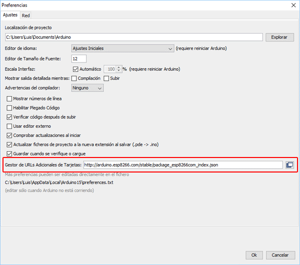
- Add URL for additional boards: Open the preferences found in File> Preferences, then where it says Manager of Additional Card URLs, copy the following link: http://arduino.esp8266.com/stable/package_esp8266com_index.json. And click the Ok button.

-
- Add the ESP8266 drivers: Go to Tools> Board: «Arduino UNO»> Board Manager ..., then in the board manager search for ESP and install the ESP8266 by ESP8266 Community. And with these steps, we have the Arduino IDE configured to program our board. NOTE: Remember that if you are going to use an Arduino or any other SoC you have to change it back again to the previous configuration. Also this installation only needs to be done once on your IDE.


After this installation, every time a code is going to be loaded to the ESP8266 remember to change the board to "Generic ESP8266 Module"
So that there is only a communication between the ESP8266 and the ESP32, without any interference by other devices, the communication protocol implemented is the "ESP-NOW", a communication protocol created by Espresiff. To make use of this wifi communication protocol, you must first identify which are their MAC addresses (Media Access Control Address). Simply, upload this code to the ESP8266, run it and open the serial monitor, then a message with the mac address will be displayed, it consists of a six-digit hexadecimal number like this: CC-50-E3-96-1D-F4. Save this number for later, since is going to be overwritten in the EMG control codes.
The EMG transceiver code for the ESP8266 can be found here, remember that when you press the upload button at the Arduino IDE you must hold the P1 button that you installed on your breadboard until the process is done at a 100%.
The code for the ESP32 to act as a signal receiver and as an actuator for the servo motors can be found here.
Luckily, for the ESP32-WROOM-32 there's a micro-USB port for connecting it to the Arduino IDE, like any other Arduino board, so there's no need of extra circuitry to program it. The ESP32 module and its .json file must be installed just as it was shown earlier for the ESP8266, you can follow the same steps, only that the address that is placed in Manager of Additional Card URLs option at the Preferences menu of the Arduino IDE is this one: https://raw.githubusercontent.com/espressif/arduino-esp32/gh-pages/package_esp32_index.json
To add that second .json file without issues with the previous one, type a comma before pasting it, like this:

Then, at the Board Manager search for "esp32" and install the module. After this installation, every time a code is going to be loaded to the ESP32 remember to change the board to "ESP32 Dev Module". At the right side of the micro-USB port in the ESP32 there is a button labeled as "boot", it must be pressed when loading code to the board, just as it was done with the ESP8266.