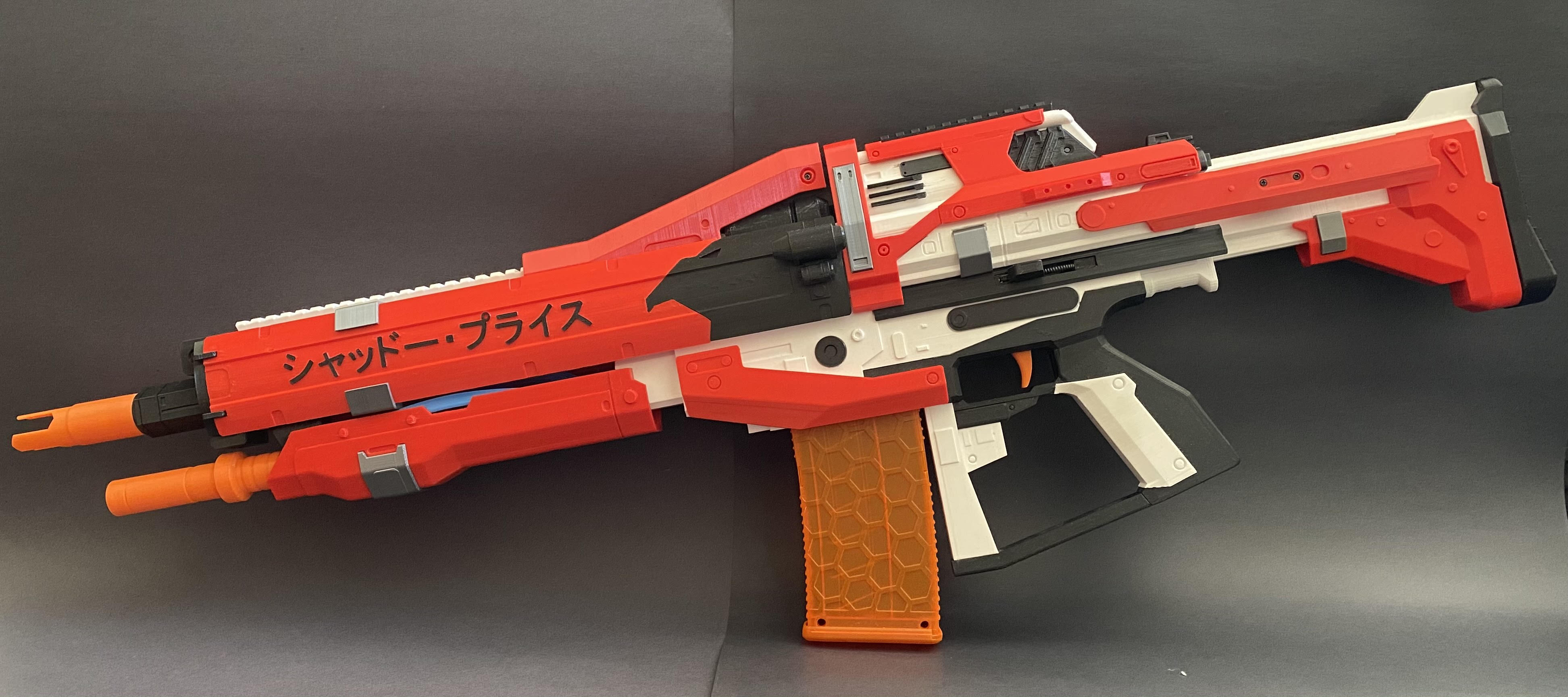
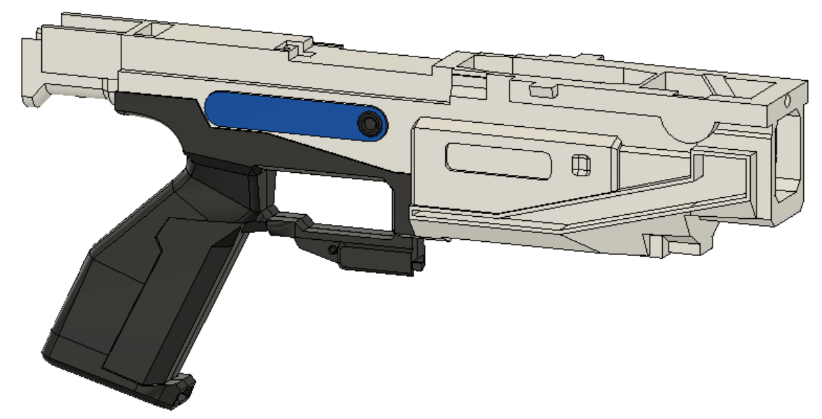
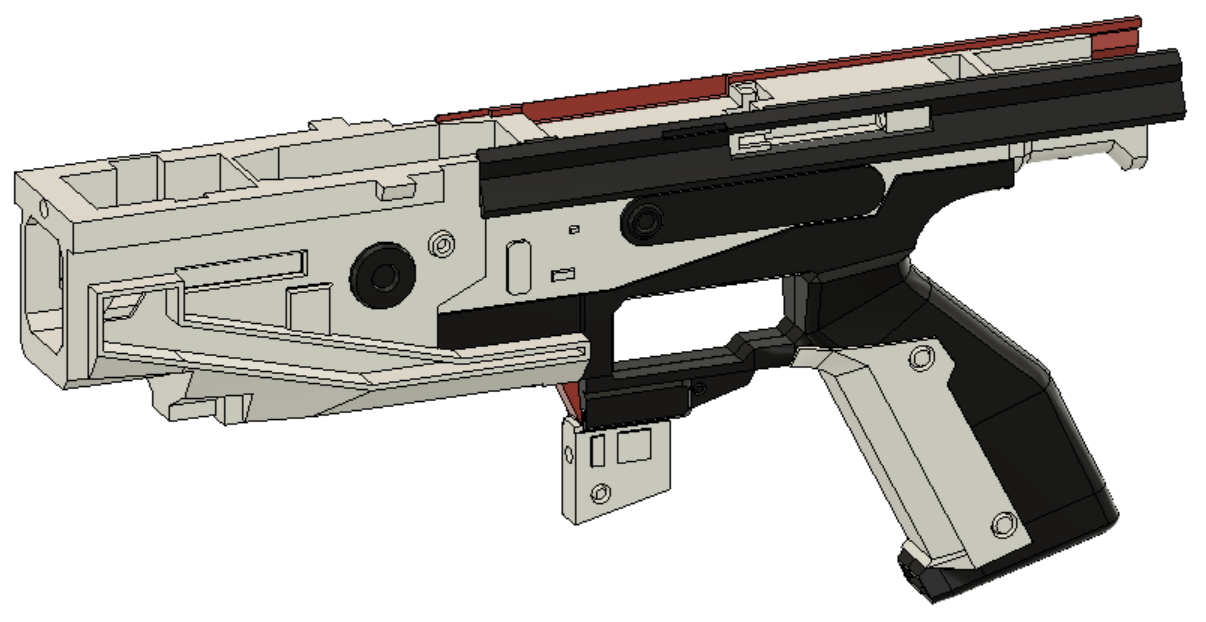
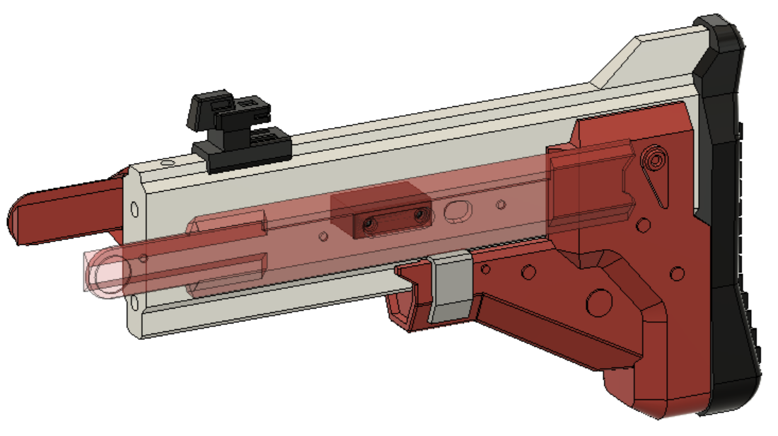
This is a Re-draw of Shadow Price with significant structural and aesthetic improvements that I made over the summer of 2020. It is now to-scale compared to in Destiny and much easier to edit. I plan to make all the other variants of stocks, barrels, and frames seen in the game. Internally, it is still BLDC flywheels and solenoid pusher, but now uses a 16 bit display ammo counter, and includes select fire. It also uses hardware to hold the blaster toghether, unlike the original which was mostly glued together. As a result, most visual components are separate parts, so even without paint the blaster should look very nice, and allows for color swaps if multiple aesthetic components are printed.
- Six 5mm x 400mm carbon fiber rods
- Five M3 x 8mm heatset inserts
- Three M2 x 4mm heatset inserts
- Five 10mm Nerf style screw
- Four M3 x 12 screws (I used hex socket)
- One M3 x 8 screw
- Four pen springs (one for trigger, two for mag release, and one for priming rod play feature)
- About 1 inch (30mm) of half inch or 14mm PVC pipe (to straighten dart as it leaves the flywheels)
- Electrical or Painters tape (to center and hold pipe at base of barrel)
- ~Four 1kg spools of filament (more if using multiple colors)
- One 35mm solenoid (designed for FTW hyperdrive solenoid so a regular one might not fit) https://flywheeltheworld.com/shop/ftw-hyperdrive-solenoid/
- Two 2300KV brushless motors (currently supports 2204 and 1806)
- Two ESCs matching motor amperage draw
- One XT-60 (or preffered) male battery connector
- Two 6mm surface mount (or breadboard compatible) pushbutton switch
- Two D2F-01L3 momentary limit switches (I used the rounded lever)
- One MOSFET or pre-built mosfet board
- One 10kΩ resistor (only if using raw MOSFET)
- One IN5408 diode (only if using raw MOSFET)
- One 10kΩ potentiometer
- One 32 x 128 I2C OLED display (https://www.dfrobot.com/product-2019.html this is the only one that I know works, but any with the same shape would work too)
- One Arduino Pro Mini
- High Amperage wires for battery to MOSFET and ESCs
- Small wires for Arduino Connections
- OPTIONAL: JST or other connector type for removeable connections (good for troubleshooting)
- OPTIONAL: Solderable breadboard/raw PCB for wire management

- Glue together the two handle halves (use the lower and knuckle guard bottom to align)
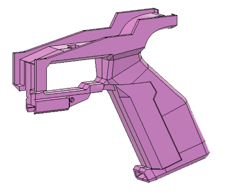
- Glue handle into the lower
- Glue details into lower
- Glue lower covers to lower (make sure to have them align with the cut out for the solenoid
-
Glue lower filler into lower (make sure it is pushed all the way in)
-
Glue together the two knuckle guard pieces
- Slot mag tooth with spring into lower, slot mag release into the handle, and place the lever into the lower from below
- Snap the handle cover into place by rotating it in about the trigger guard
- Slot top of knuckle guard into lower, around the lever and mag release, then slot the tab into the recepticle in the handle and use a nerf screw to lock it in
- Press magwell covers into slots on either side (DO NOT GLUE, will need to remove later to access wires)
- Slot in prime pin and prime, place spring behind prime so it will bounce back forward after getting pulled back (can also add some lubricant to smooth movement)
- Glue detail parts into upper
- Glue top picatiny into ammo counter (make sure bottom surface flush, the assembly slots into the upper)
- Glue details into archway
- Glue archway, top cover, and tail together (assembly called the frame)
- Cut a 400mm carbon fiber rod in half, and glue into top and bottom of stock filler. Align by first putting rods into upper and lower, then pushing stock filler into them. (all other parts can be optionally glued in, but I suggest against it)
The blue spirals are the M3 heat set inserts, can be added now or later, it does not matter
- Glue the battery tray strap into the battery tray
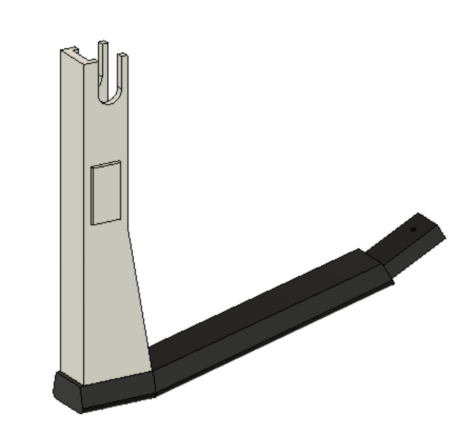
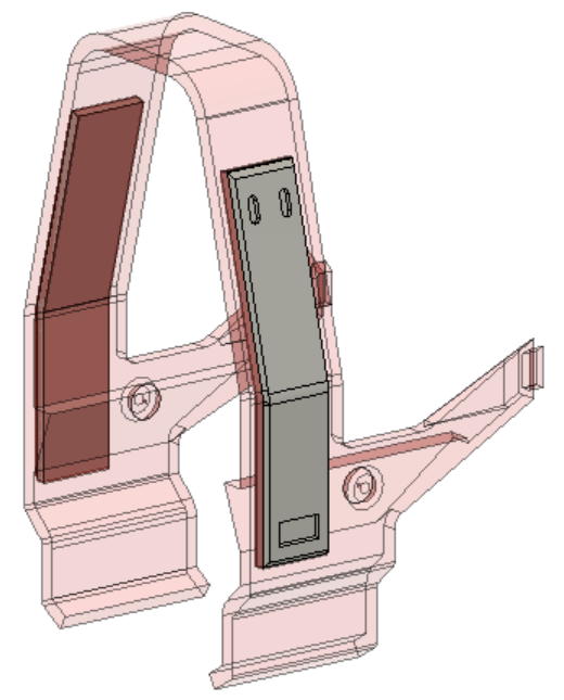
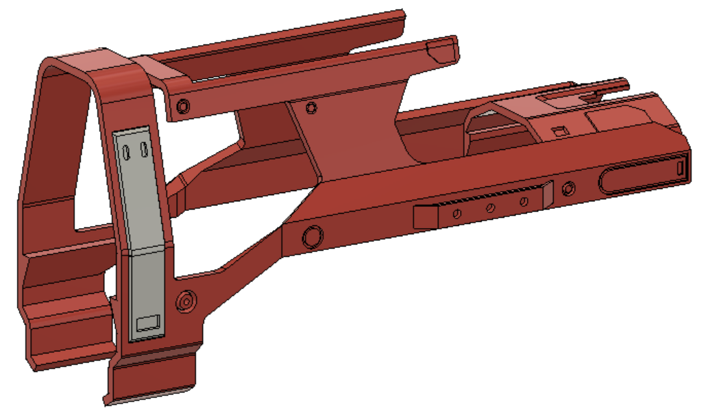
- Slot details into stock, and slide stock into dovetails. Place buttstock on back of stock filler. Screw one side of the stock panels into the standoff, then run standoff through the stock filler and screw on other side (they get centered by the upper so dont worry about lateral spacing)
- Prepare locking lug by inserting the two M3 heat set inserts into the holes
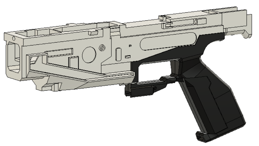
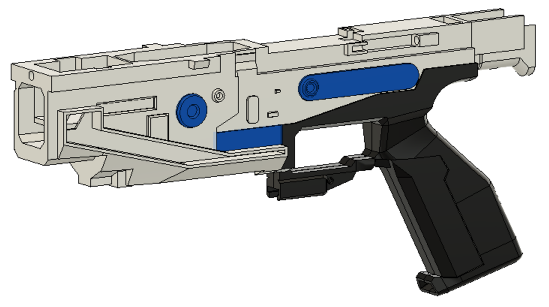
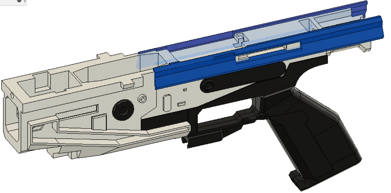
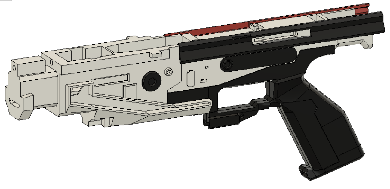
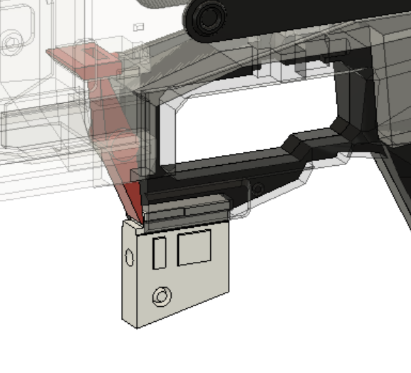
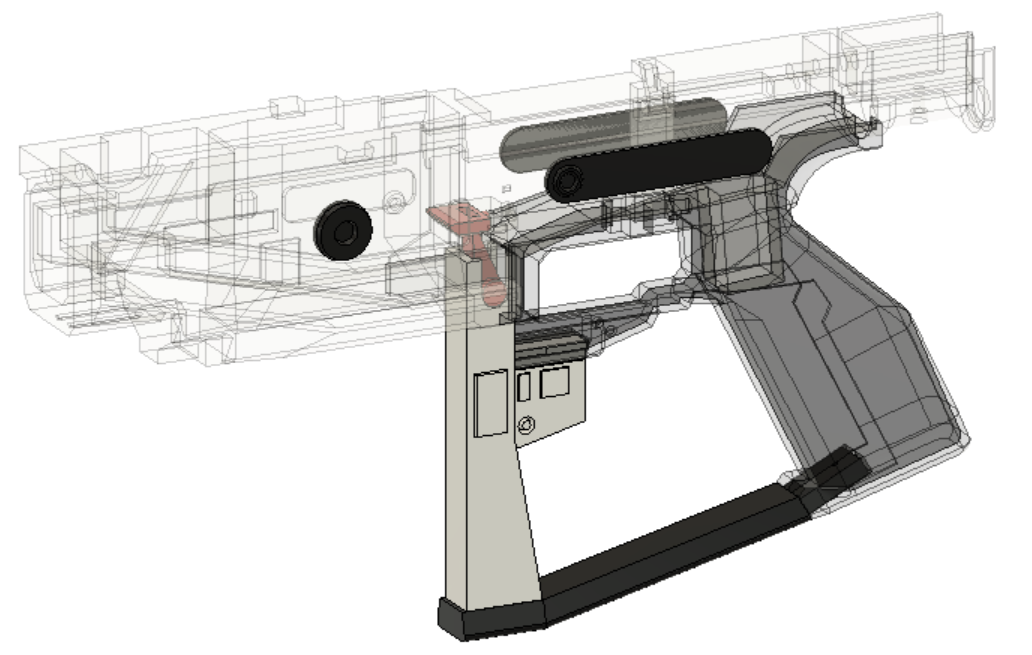
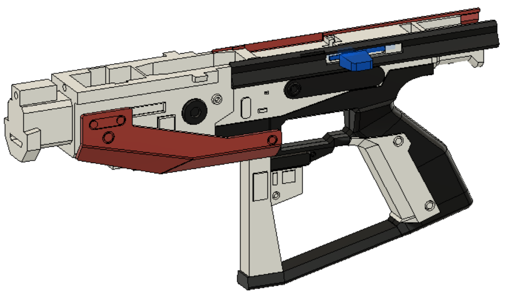
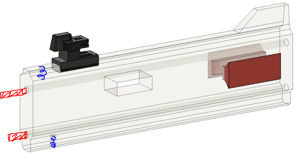
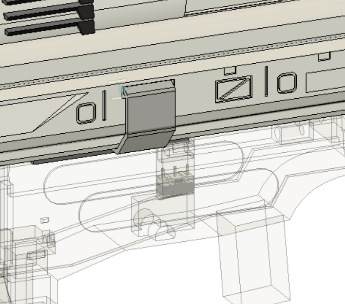
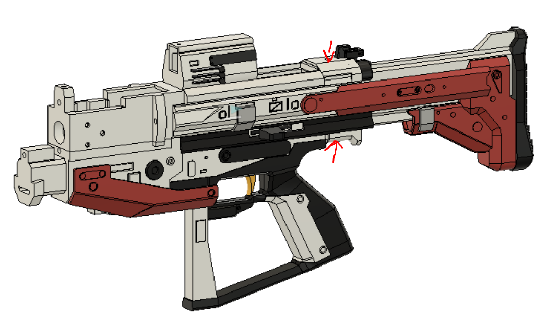
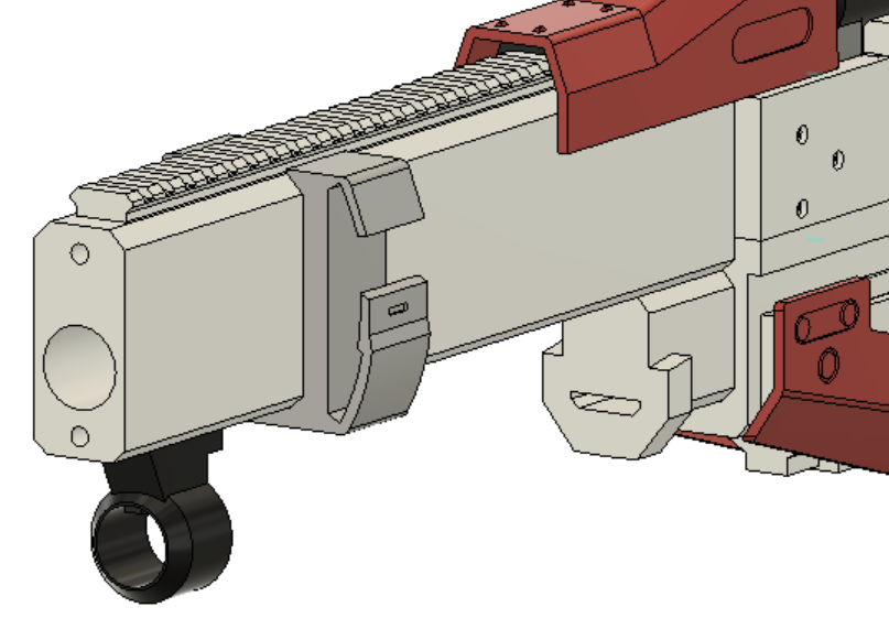
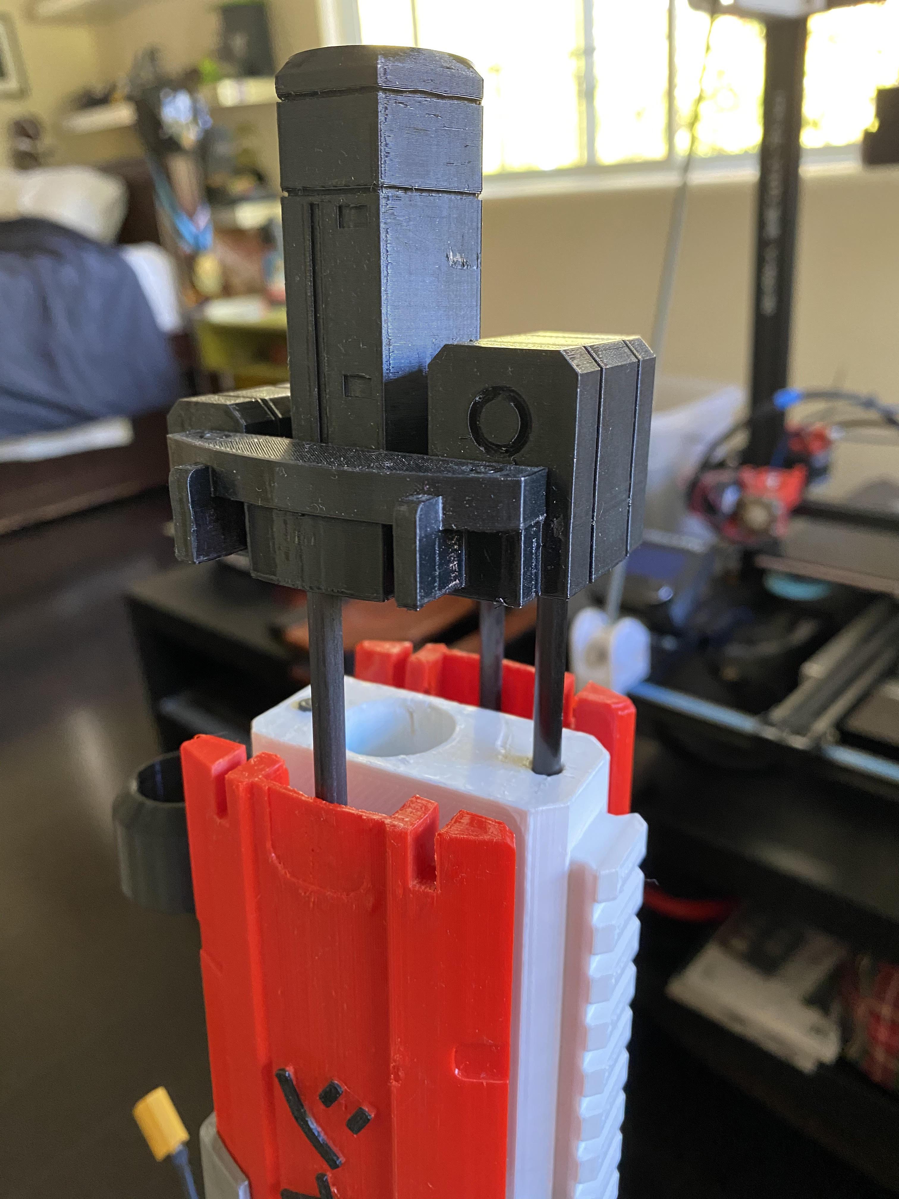
- At this point you can begin wiring up the blaster, all electronics are housed in the upper other than the trigger switch. Below are photos of switch placement. Wire all switches as normally open, and the mag sensor switch will need the tabs cut down a little if they are too long (the mag sensor can also be flipped upside down if it registers more consistently)
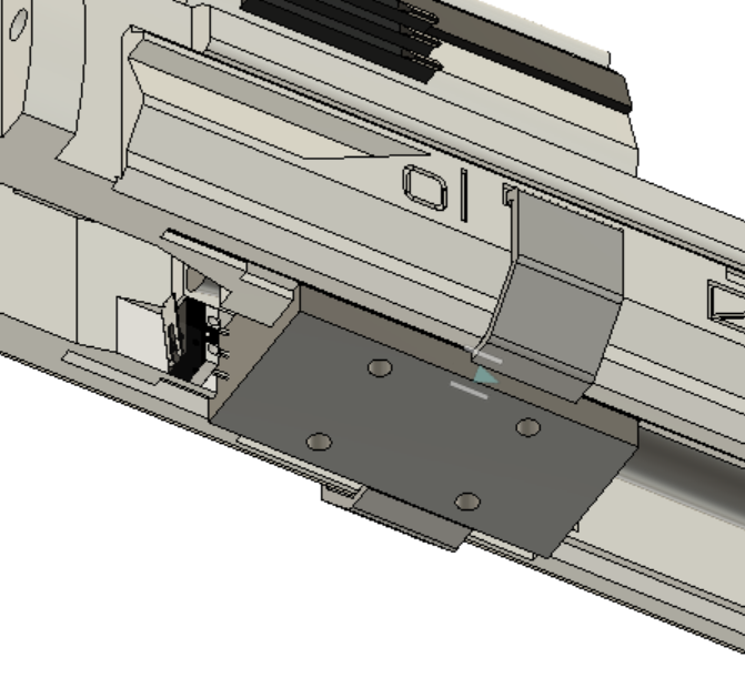
Parts removed for visual clarity
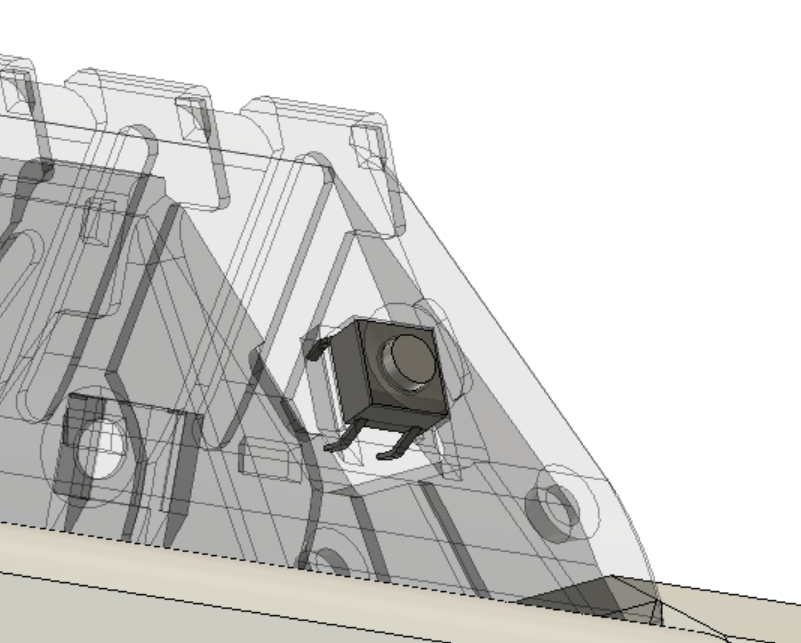
Place a switch on both sides
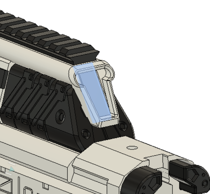
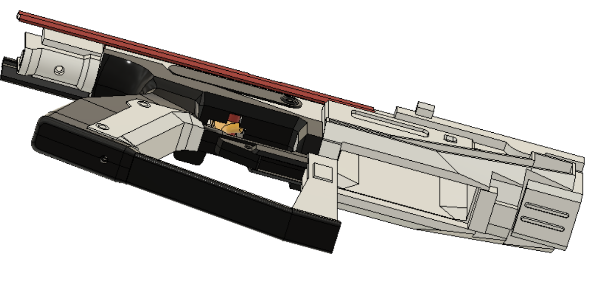
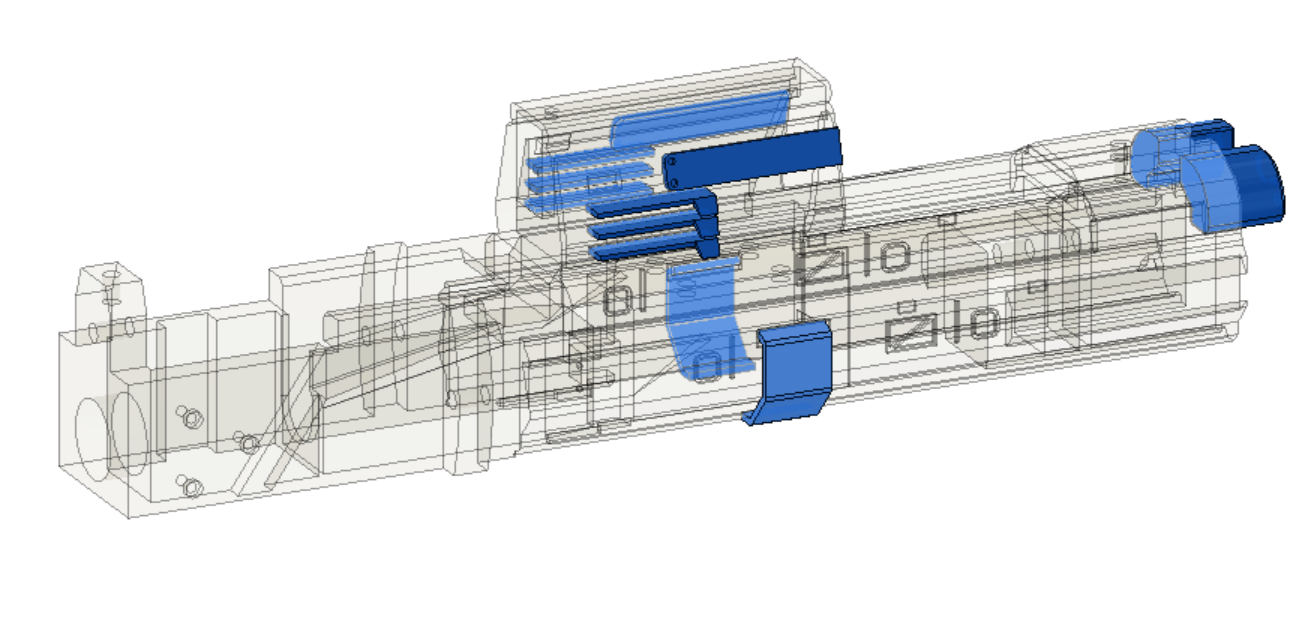
Make sure not to glue in the OLED or it will make accessing the potentiometer harder
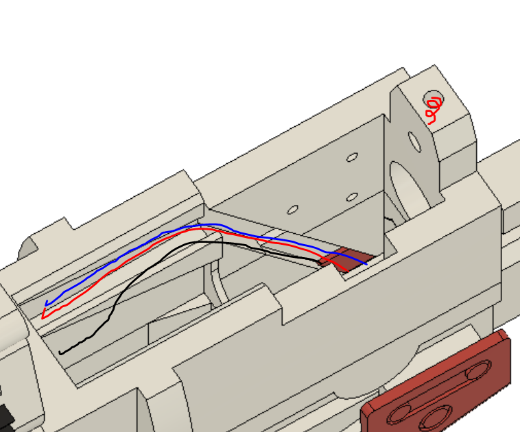
Route ESC and battery cables through this slot (it is ok for them to spill over into the open space, it is well above the magazine and gets covered up)
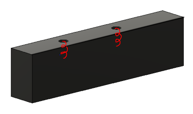
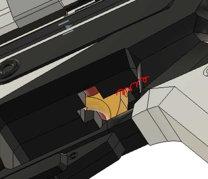
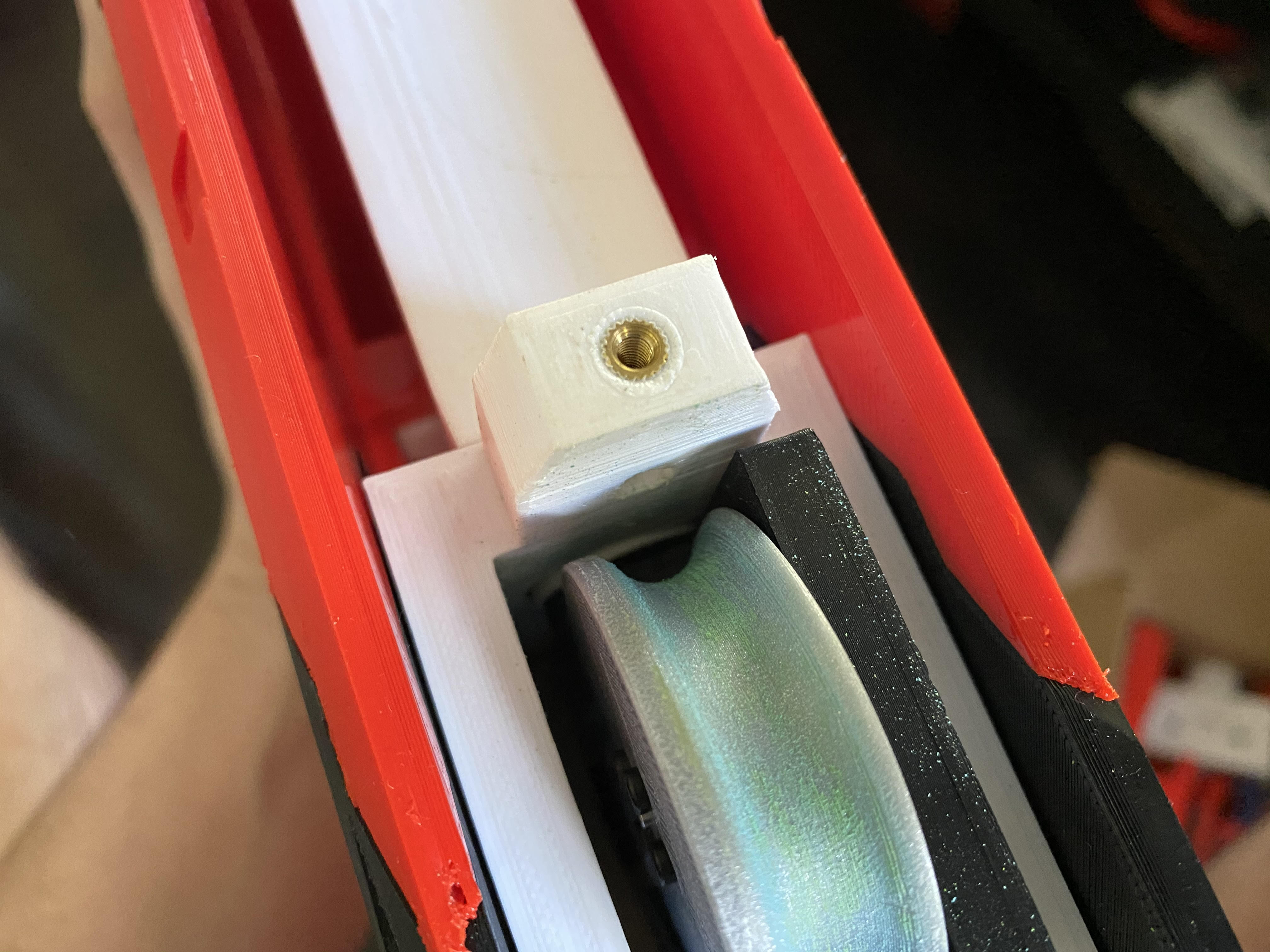
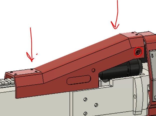
Add the final M3 Heat set insert into the hole marked by a red spiral
- Once all the wiring is done, Screw together the flywheel cage assembly, and add in the three M2 heat set inserts to the cage (be careful to not melt through the top of the cage or it will interfere with the flywheels)
- Slot trigger and trigger axle into the hole in the trigger well, and add the final pen spring in the hole behind it (rotate them in then push up until it snaps in place)
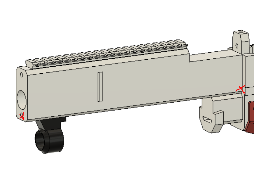
- Slot stock assembly into back of upper and lower, and screw in the top and bottom
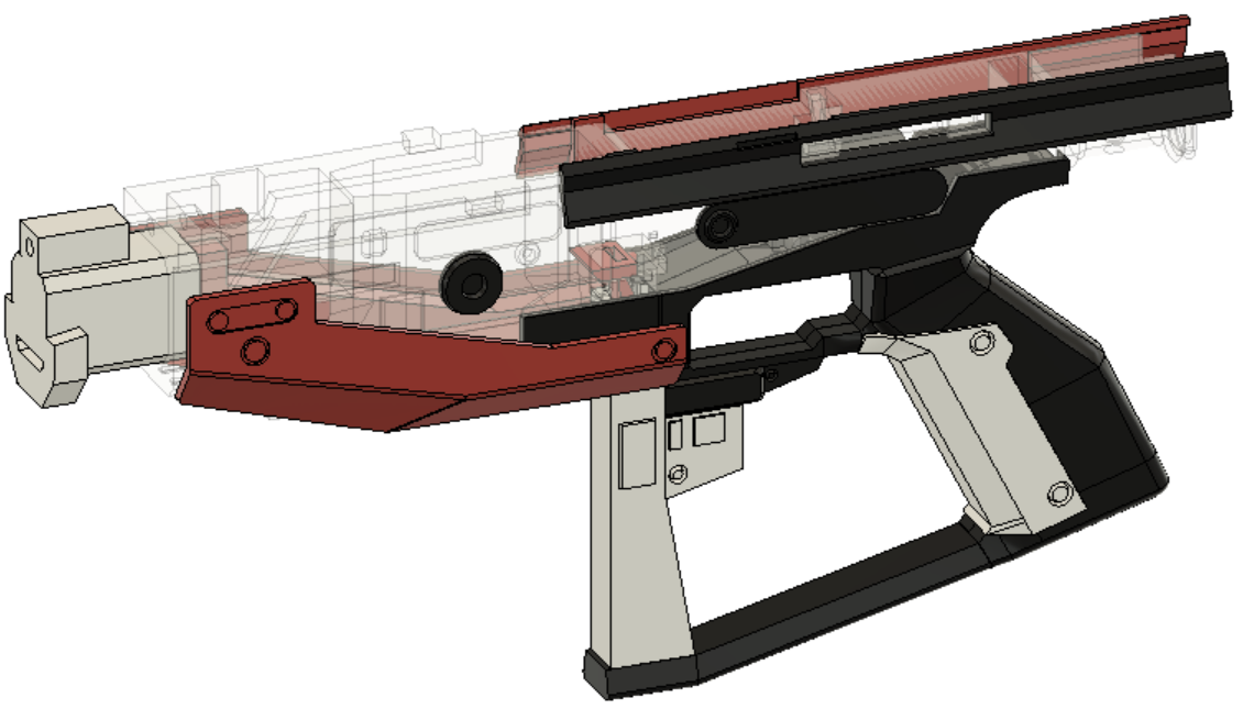
- Place the barrel filler over the lower filler and slot in another carbon fiber rod (DO NOT GLUE) making sure the rod is flush against the inside of the lower and the front of the barrel (you will have to cut the rod). Also dont forget to place the lock in the front slot of the barrel filler and the barrel rail in the slot on top
- Place the center filler over the flywheel cage and lock it by slotting the locking lug from behind and another carbon fiber rod from the front. This rod should stick out a little at the front because it sticks into the barrel faceplate, so make sure to check its length and have it flush against the inner wall of the upper. Also screw it down with the longer M3 screws
- Wrap tape around the small length of PVC and push it down the barrel so it is flush with the front of the flywheel cage
-
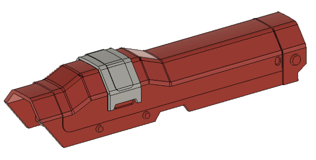
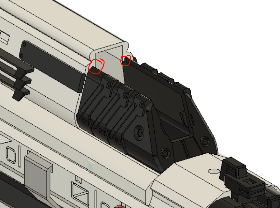
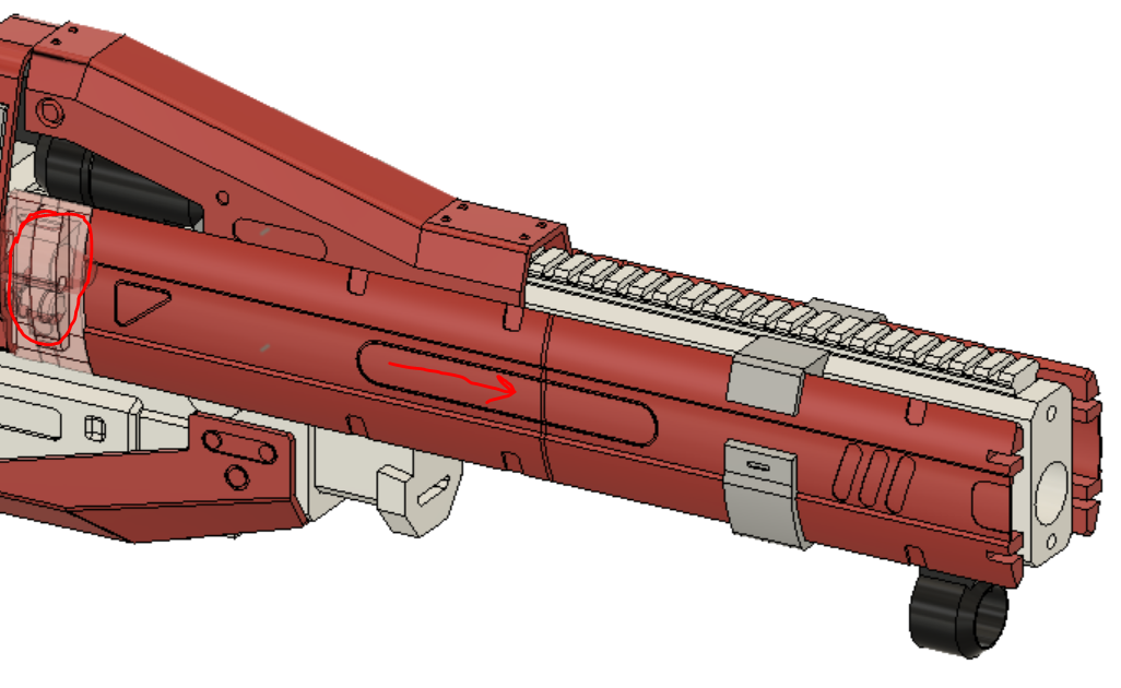
Once all the electronics are inside, snap the ammo counter cover into the upper by squeezing the sides, placing it into the cavity, teetering it back and snapping the sides out (make sure they snap past these tabs)
-
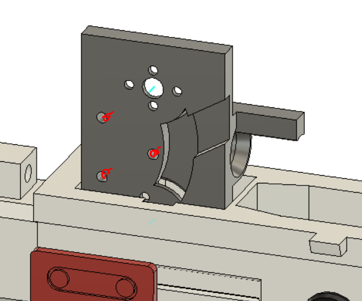
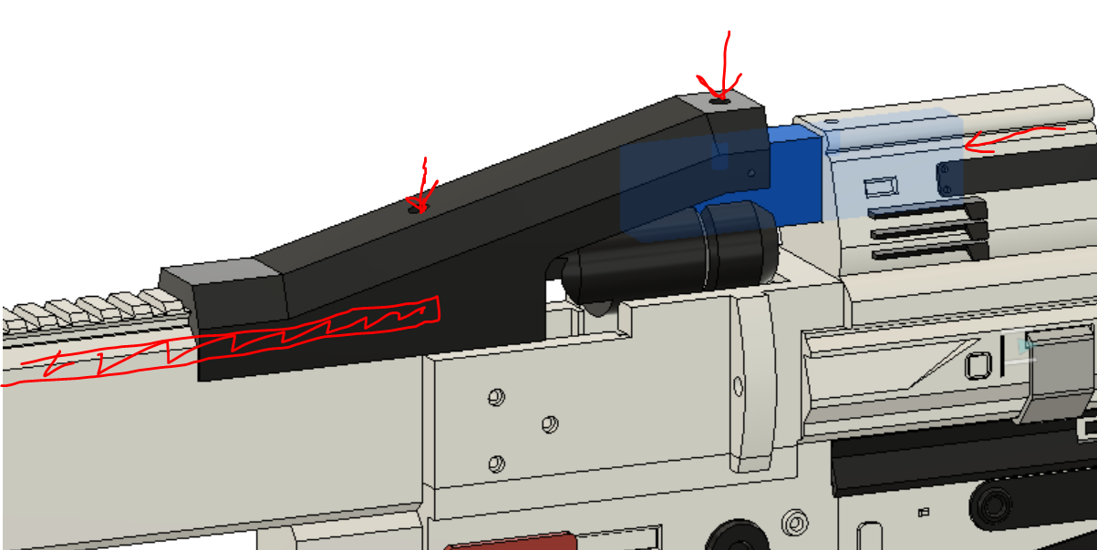
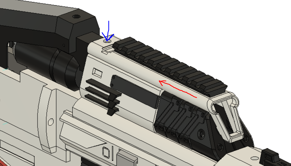
Slot ammo counter and picatiny assembly over the electronics and OLED (red arrow), then rotate the oled into the slot on the ammo counter and use the shorter M3 screw to lock it down (blue arrow)
- Snap the frame over the upper, it will lock in at the front, back, and slot over the cut out in the ammo counter
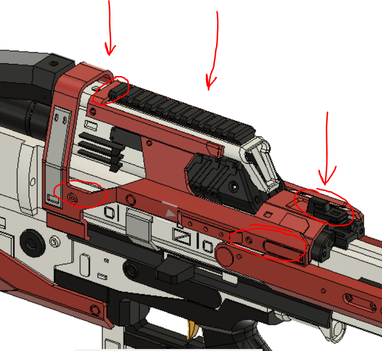
- Snap in the top cowl and add the last Nerf screw to hold it down
- Slot on the barrel clip, it will snap in place once in position
- Stack up the three parts of the side panels and push a carbon fiber rod almost all the way through them, but dont go through the rectangular opening at the end
- Push the panel assembly through the barrel clip from the back, and once far enough the opening in the panel will lock over the arc pop-out in the upper and lower
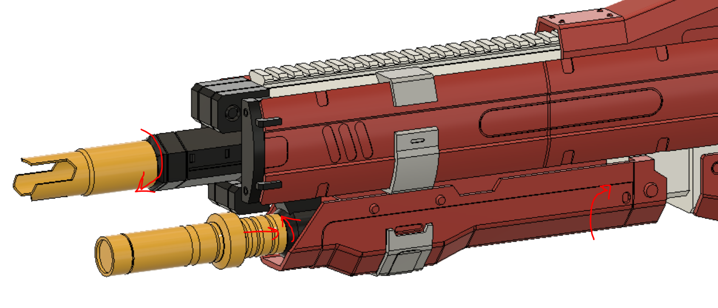
- Slot on the barrel. It will mesh with the top and both panel carbon fiber rods, and sit flush against the barrel filler front surface and lower rod, so they all need to be at the correct length for this step (tip: if you have problems aligning the rods, push them into the barrel FIRST so you just press the assembly into position, slotting all the rods at the same time)
- Screw on the muzzle, snap in the battery tray and lock it with the second barrel and you are done!
You will need four external libraries to run the code for this blaster.
They are:
- JC button library https://github.com/JChristensen/JC_Button
- built in pullup resistor commands, inversion, and debouncing
- Adafruit GFX and SSD1306 (downloadable thru arduino library manager)
- controls OLED display with easy to understand commands
- Ammo counter (self written library, available in the code directory)
- ammo counter code written by Monty Choy converted to a library
Current issues to work out:
- more descriptive interface with user
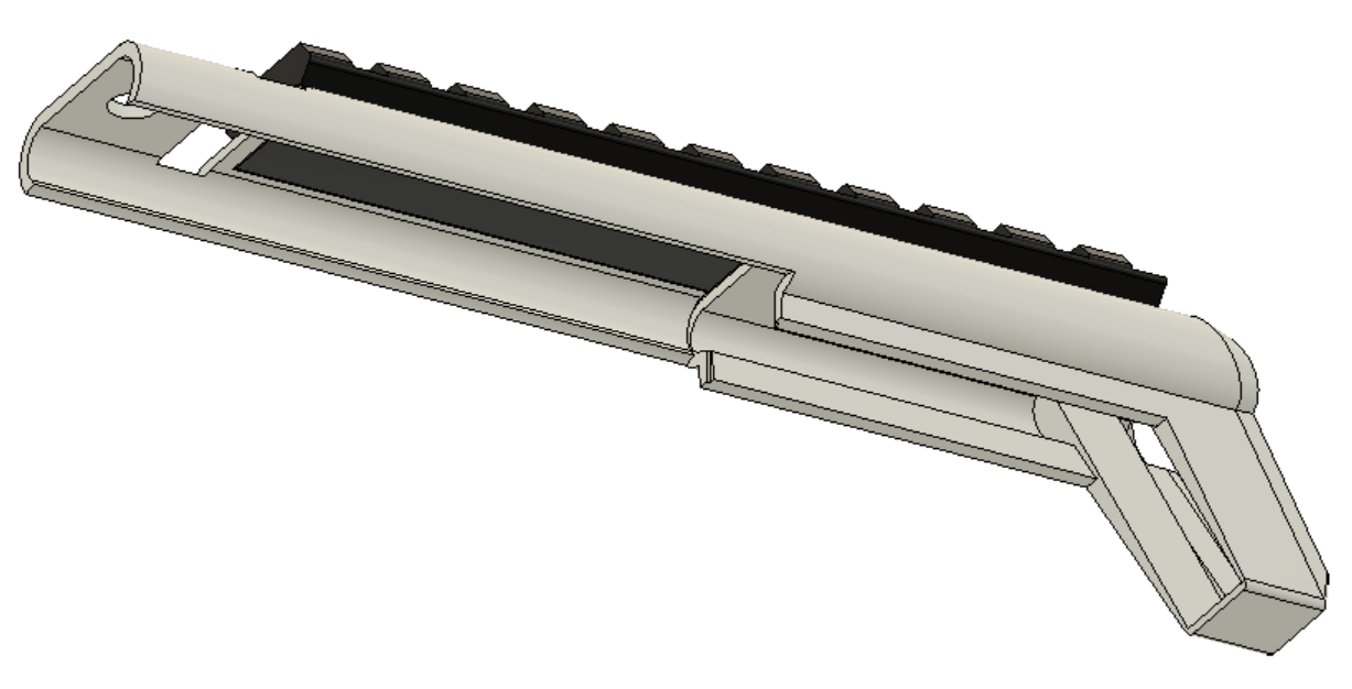
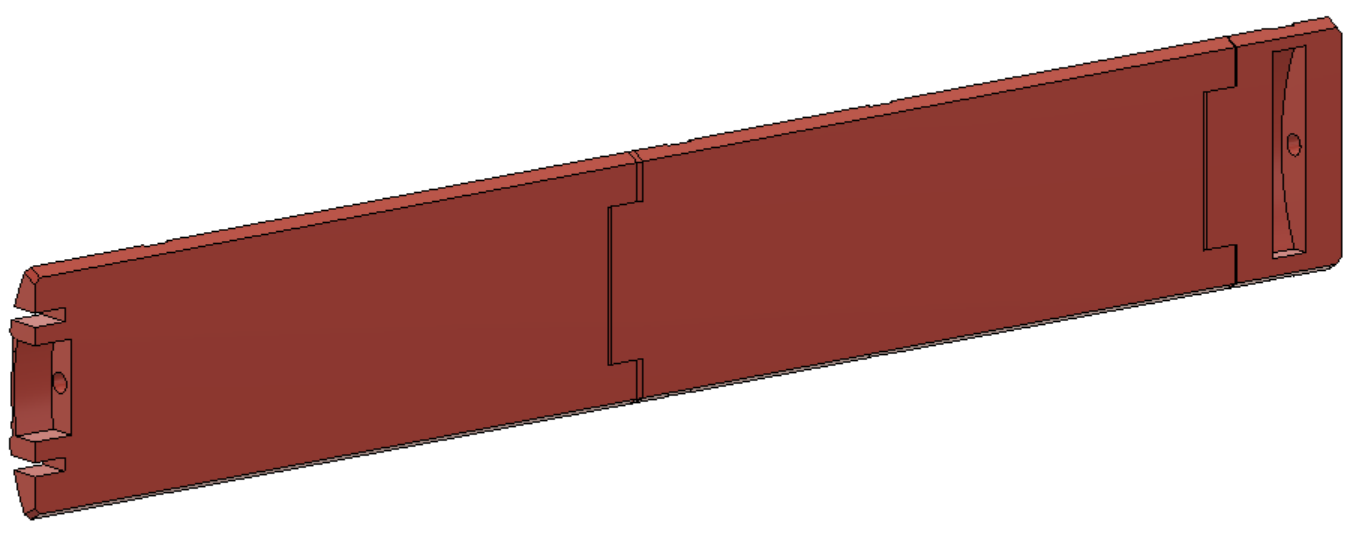
If you would like custom panels like the ones on my personal blaster (seen at the top of the read me) a step file is available in the STEP directory.
The provided STEP includes the two panels as single, large parts and a new barrel clip that does not extend into the central cutout. As long as you dont fill in the hole for the rod, the slot in the back, or the cutouts that mesh with the barrel in the front, you can add anything you want to the panels. If your printer is not large enough for a full panel (like mine) you can make a design along where you plan to cut the panel, like the eagle head on my personal blaster. Have fun with it and personalize your blaster to your tastes!
They are massive, like 60MB, so if you want them just shoot me an email.
This work is licensed under a Creative Commons Attribution-NonCommercial-ShareAlike 3.0 Unported License.
