Shadow Price is the culmination of many years of CADing, which I had to learn along the way, and Coding, most of which I was taught by @mochoy. It uses brushless motors for the flywheels, a solenoid pusher, and has an integrated IR beam based ammo counter. The shell is based off of the stock weapon model for an auto rifle in the video game Destiny, and my personal blaster is painted like Shadow Price.
The STLs for all components are not inhenretly in the correct priting orientation, however there are large flat areas on all parts so use your best judgement when printing and print on these faces
All minor changes to this document will be dated and placed at the bottom, major changes will be noted at the top here
Note: This version uses tighter tolerances on all print surfaces. You will likely have to file the removeable components to get them to slide past each other.
For this Blaster you will need:
- 18 Regular Nerf screws (10mm long)
- 10 Small Nerf screws (5mm long)
- two small washers that will not slide over the main screw heads (or switch two of the small screws for something like the washer screws that are used on Stryfe mag releases)
- A small extension spring for the trigger
- A small compression spring for the magazine release (pen spring works)
- Optional:
- An 8-32 or M5 machine screw and nut (to hold up butt plate)
- An Arduino Pro Mini 5V/16MHz
- A small solderable breadboard
- two .56" 7 segment displays
- two resistors (based on the color of your display)
- two 7 segment decoders (make sure they are the same type as your displays)
- two 5mm breadboard compatible momentary push buttons
- A 3mm IR break beam
- A small limit switch
- 22 gauge wire
- Heat shrink
- Optional:
- Multiple colors of wire (to differentiate each button)
- Bread board jumpers (for creating protoboard)
- Crimp connectors (for power and ground from ESC-BEC)
Firing System Electronics
- An Arduino Pro Mini 5v/16MHz
- A 10K Ohm potentiometer
- A medium sized limit switch
- A male battery connector of your prefrence
- Two ESCs with BEC that are rated up to 3s and have a high enough amperage for your motors
- Two 2204-2300Kv brushless motors (currently working on adding support for 1806 sized motors as well)
- A 35mm stroke 12v electric solenoid
- A 1N540x Rectifier Diode
- A IRLB3034PBF MOSFET
- A 10K Ohm resistor
- 22 gauge wire
- 16 gauge wire
- heat shrink
- Optional:
- 5mm bullet connectors (for removeable ESCs and easy polarity switching)
- Crimp connectors (for power from ESC-BEC and to keep small control cables organized)
- Suild's MOSFET board 2 (as a replacement for all the MOSFET components)
To Start, you will need to download the JC Button Library by Jack Christensen. If you dont know how to download a library to your Arduino IDE this is a good guide that I used, just scroll about half way down and there are two mehtods to download the library. There are only two areas in the code you should ever realistically need to change, the pinout and revSequence. The pinout is simple:
#define TRIGGER_PIN 9
#define MOTOR_PIN 10
#define ACTUATOR_PIN 11
#define POT_PIN 1
#define FIRE_MODE_PIN 7
- TRIGGER_PIN is for the trigger microswitch.
- MOTOR_PIN is for both of the signal wires from the ESCs, so make sure you splice the wires together at some point.
- ACTUATOR_PIN is for the signal wire coming off the solenoid MOSFET, in the case of the MOSFET board 2 from Suild it would be a wire coming off the gate pin.
- POT_PIN is for the 10K Ohm potentiometer signal pin, the wire that comes from the middle tab.
- FIRE_MODE_PIN is for an unutilized two position switch that would change between full auto and three round burst. While the code is written for this, there is no mounting geometry in the 3D prints, so you would have to download the .step file in the prints folder and model it in yourself.
The other area of code you might need to change is:
void revSequence(){
  flywheelESC.writeMicroseconds(1860);
  delay(map(analogRead(POT_PIN), 0, 1023, 150, 50));
  flywheelESC.writeMicroseconds(map(map(analogRead(POT_PIN), 0, 1023, 0, 100), 0, 100, 1250, 1650));
  delay(70);
}
In this function you might have to change the delays based on your motors' spin up time. In the first delay, the only values you might need to change are the 150 and 50, which determine how long you need the motors to accelerate for. Effectively, the motors accelerate the greatest when an immediate command to full speed is sent. What this line of code is doing is using that concept to put the motors at max acceleration for longer when the potentiometer is set to a low speed and accelerate for less time when at the optimal speed. Without this line of code the spin up times for all motor speeds would be significantly greater, so change these values only if your first dart fires significantly harder than the rest of your darts when holding the trigger.
The second delay at the end of the function is less complicated, and the only value you might need to change is the 70. Once the motor has been told the desired speed (from the previous line of code) it needs a moment to reach it, so the delay is just waiting for the motor to reach that speed, so if your blaster constantly jams when firing the first shot increase this delay, and if you feel like the first dart takes an eternity to fire decrease the delay. If you are going to play with this number I suggest you increase or degrease by units of 5 until you reach the minimum delay where your blaster wont jam.
If you use a different ESC than the 12A AFRO that I use, the min and max speed in microseconds (1860) might be different, and since you will use different motors than the 2204-2300KV Turnigy Multistar Elites (because they are discontinued) the minimum firing and optimal speeds in microseconds (1250 & 1650) will be different.
To find the max and min speeds in microseconds you will have to refer to the instruction manual that is associated with your ESC, or just test values until you find the threshold value where the motors begin to spin (the minimum microseconds) and find the threshold value where the motor speed does not seem to contimue to increase. Once you find these values just ctrl+F in the arduino IDE and switch out every 1060 & 1064 for your new minimum value and switch out every 1860 & 1864 for yor new maximum value (including in the setup code). Make sure all of these test you conduct inside the assembled blaster, since it is dependent on the solenoid firing
To find the minimum firing and optimal speeds you will have to rely solely on testing. For minimum firing value, increase from the minimum value in incriments of 10 until you can fire 10 shots full auto without jamming. For optimal value, degrease from max in incriments of 10 until the FPS of the dart begins to drop, and you'll need a chronograph for this test (or just look at range with measuring tape, but that will take longer and require more walking). These tests can be conducted outside of the blaster, with you manually feeding the darts into the flywheel cage, but it's better if you conduct them inside the blaster since the results will be more realistic.
I will preface this section by saying that this ammo counter is not exlusive to Shadow Price, if you can find some other low current 5v power source to plug it into it will work completely independent. The amount it can count up to is also expandable, so if you want to make an ammo counter for your backpack fed blaster feel free to use this design, good luck with counting how many balls you put in at the beginning though.
Just like before the pinout is relatively simple
#define DIG_ONE_A 2
#define DIG_ONE_B 3
#define DIG_ONE_C 4
#define DIG_ONE_D 5
#define DIG_TWO_A 6
#define DIG_TWO_B 7
#define DIG_TWO_C 8
#define DIG_TWO_D 9

#define IR_BEAM 14
#define MAG_SIZE_UP 10
#define MAG_SIZE_DOWN 11
#define MAG_SENSOR 12
- DIG_ONE_A-B and DIG_TWO_A-B are the A-B signal pins on the 7 segment decoders, ONE and TWO being for the tens and ones digits, respectively.
- IR_BEAM is for the signal pin of the IR break beam sensor.
- MAG_SIZE_UP is for the button that increases the magazine value.
- MAG_SIZE_DOWN is for the button that decreases the magazine value.
- MAG_SENSOR is for the limit switch that goes inside the magazine well.
If you are using this ammo counter for Shadow Price or any other under-100-dart-capacity blaster the only other variables you might change are:
int BASEmag  = 17;
int MAXmag   = 35;
- BASEmag is the value the ammo counter will show on boot up. You'll be able to change this value using the up and down buttons, so it doesn't really matter what this value is as long as it's less than the MAXmag value; I like putting it as the capacity of my first magazine in my loadout.
- MAXmag is the greatest value the ammo counter will display, and the value at which it switches back to 0 if you keep hitting the MAG_SIZE_UP button. Make this value the capacity of your largest magazine you would put into the blaster; In my case the largest magazine I own is the 35 round drum.
Now, if you want to expand this ammo counter to three digits (999 rounds max) or four digits (9999 rounds max) its pretty simple.
- Repeat the code in
void func()that displays the ones position for every added digit (I suggest you put it at the end of the function to keep the code organized). - Replace the variable in the
digitalWrite();on your repeated section with the new pinout for your extra digit(s). - Replace the conditions in the DIG_ONE display code with your new highest values (e.g. replace the 10,20,30, etc. with 100,200,300, etc)
- In decending order, update the conditions for the new digits (e.g. replace the %10 == 1,2,3 etc with %100 == 10,20,30 for digit two, and then leave the conditions alone for the last digit).
- Update the BASEmag and MAXmag to values that better reflect your new ammo capacity.
If this didnt make sense feel free ask via reddit (u/Band3rsnach) and I can help, but none of this last bit is required for Shadow Price.
To save time in generating these images I've placed multiple parts on a single print bed. I am NOT suggesting you print multiple parts at once unless you are confident in your printer's ability. As a general rule, internal features will not need any support, and external features will require supports (if you want the blaster to look pretty). A few parts (tail, stock panel left, trigger well left) have extrememly thin surfaces that are for bridging or to reduce supports. If you are confident in your printer's ability to bridge use them, if not the surfaces should not cause any problems with supports.
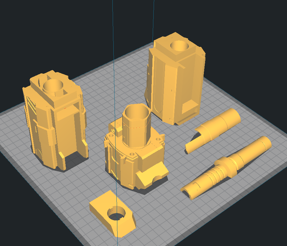
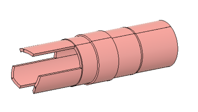
Depicted: 3X Barrel Tip, Barrel Front, Barrel Middle, Barrel End, 2X Key, Lock
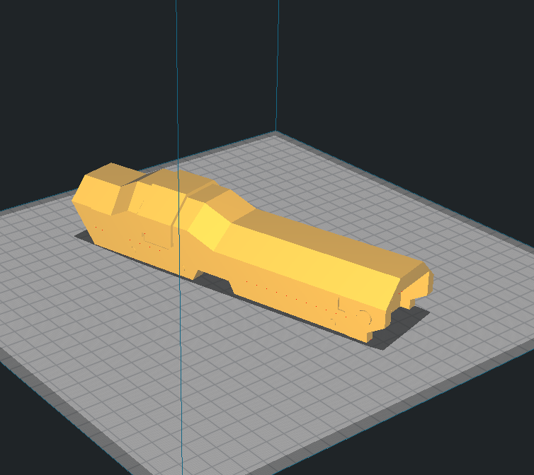
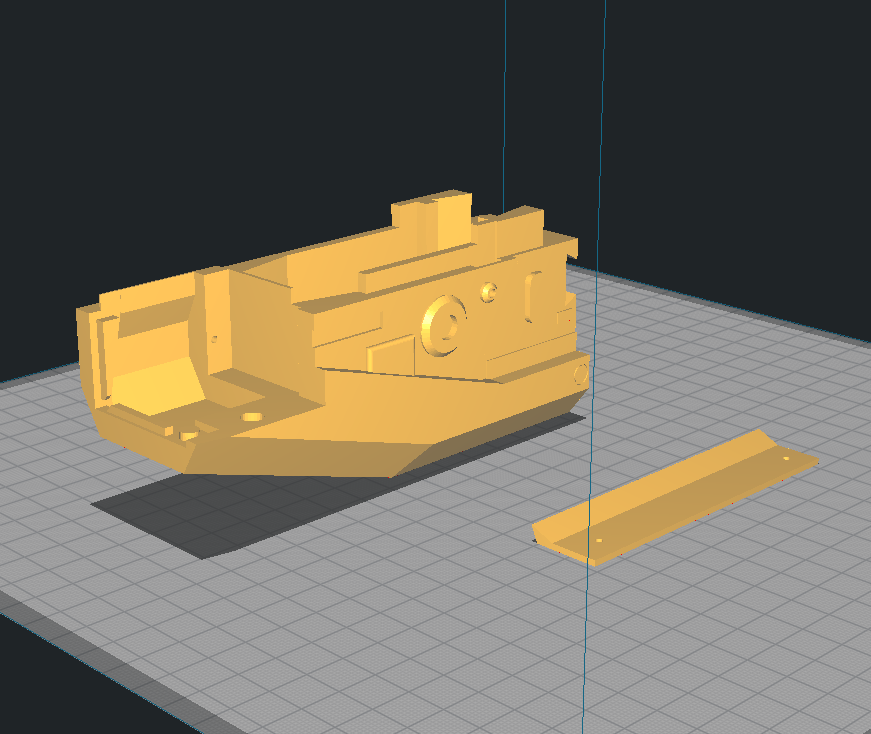
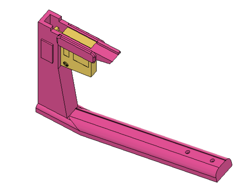
Depicted: Battery Tray
Depicted: Handle, Knuckle Duster, Left & Right Grill, Bottom Dovetail, Pusher Cover, Solenoid Cover, Top Dovetail, Trigger
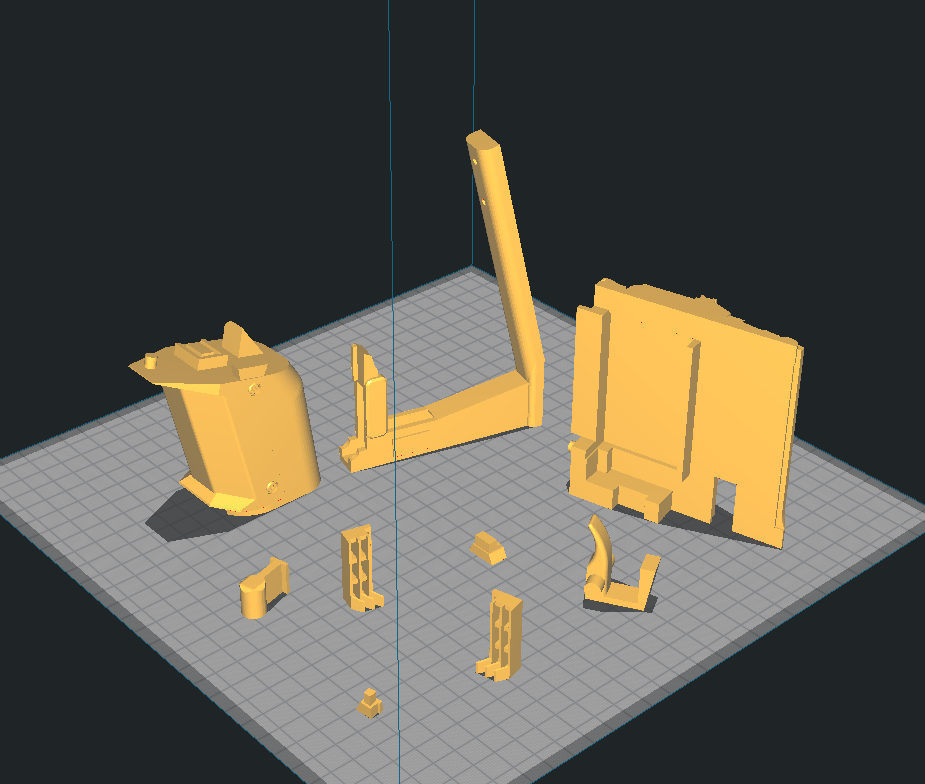
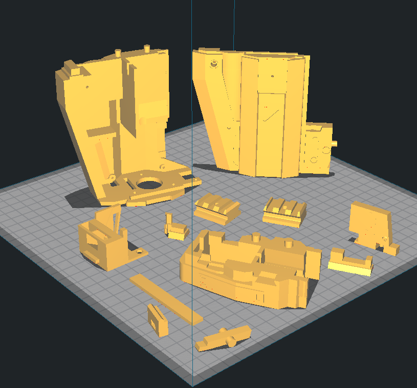
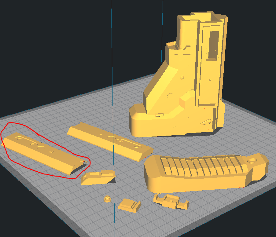
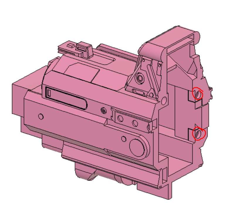
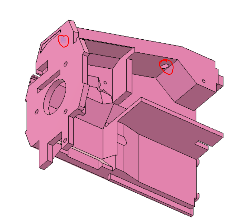
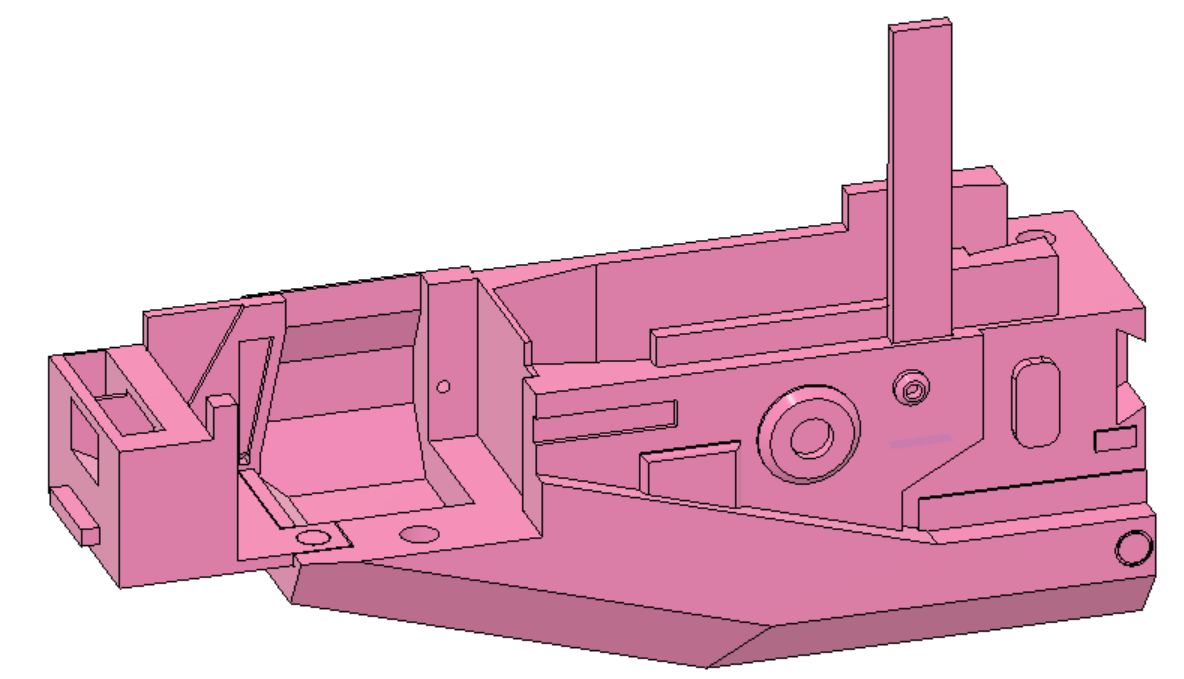
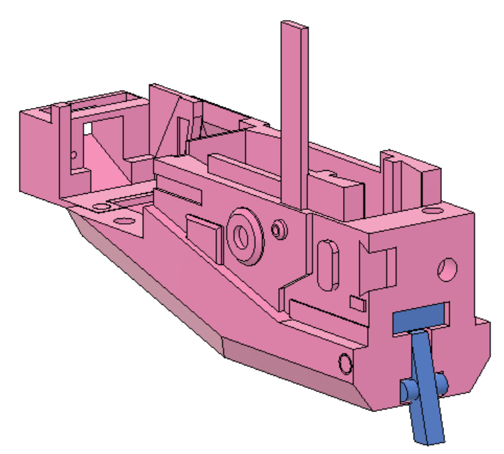
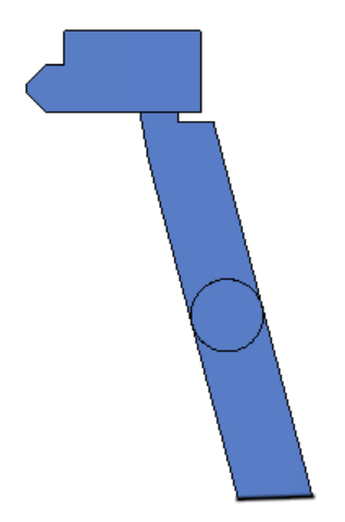
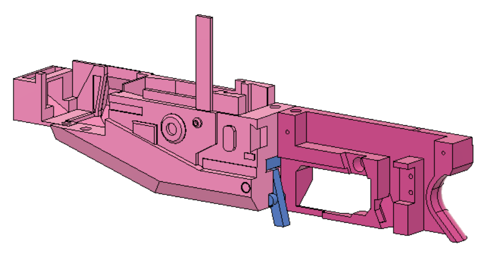
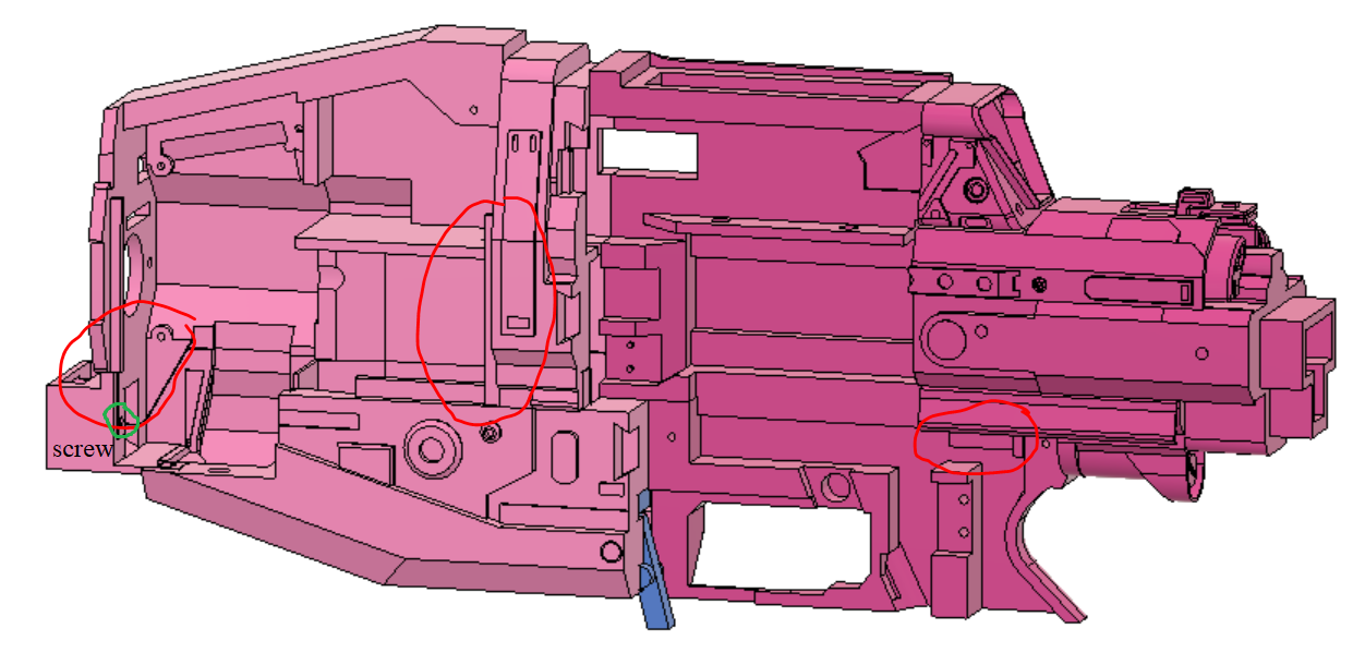
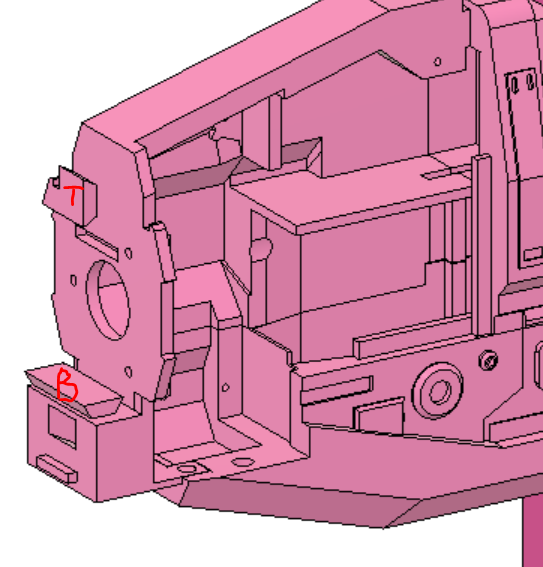
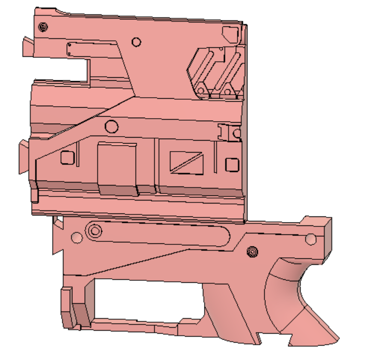
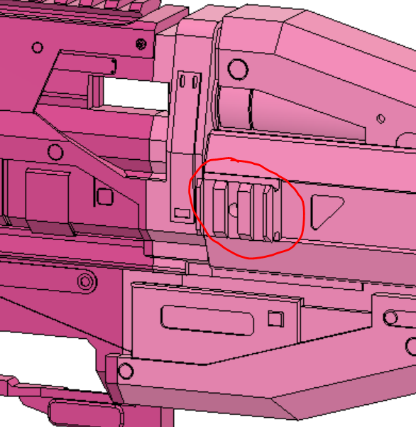
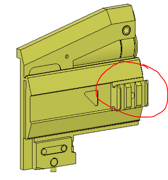
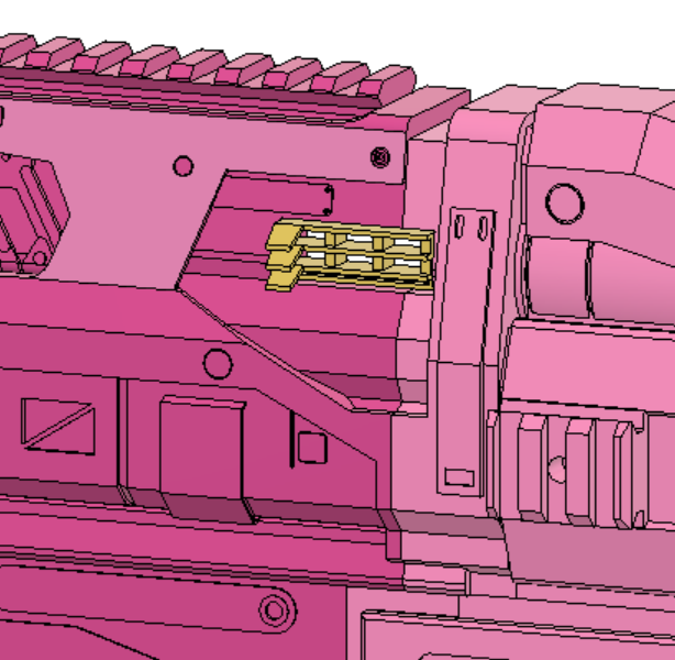
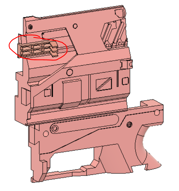
Depicted: Solenoid Mount, Tail, Tail Dovetail, Trigger Well Left & Right
The thin surface circled in red on Trigger Well Left is a built in support, and the Tail has a thin surface for bridging inside it.
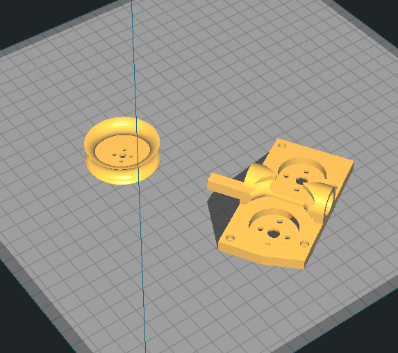
Depicted: Flywheel Smooth, High Crush Flywheel Cage
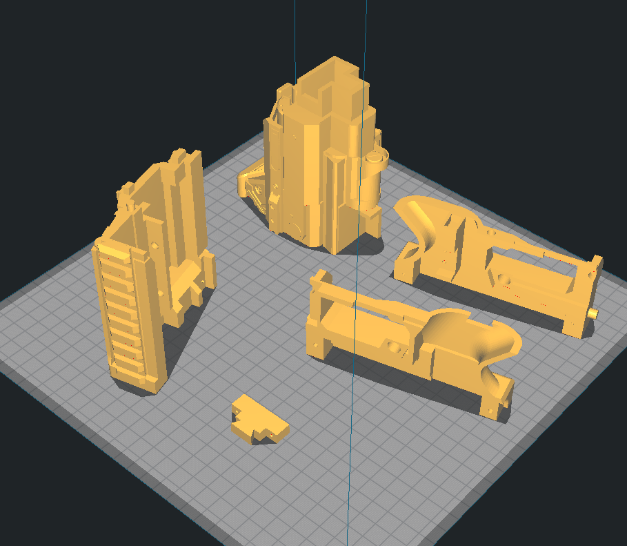
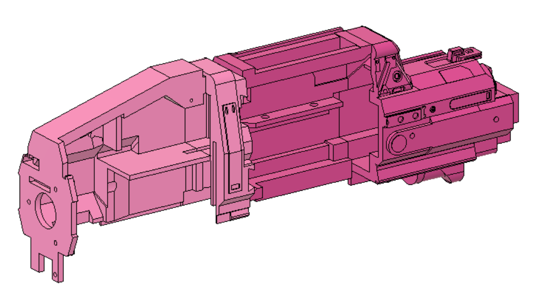
Depicted : Alignment Bar, Archway, Battery Tray Latch, Bottom Dovetail, Cage Mount, Flywheel Cover, Mag Release Lever, Mag Tooth, Magazine Release, Picatiny Left & Right, Top Dovetail
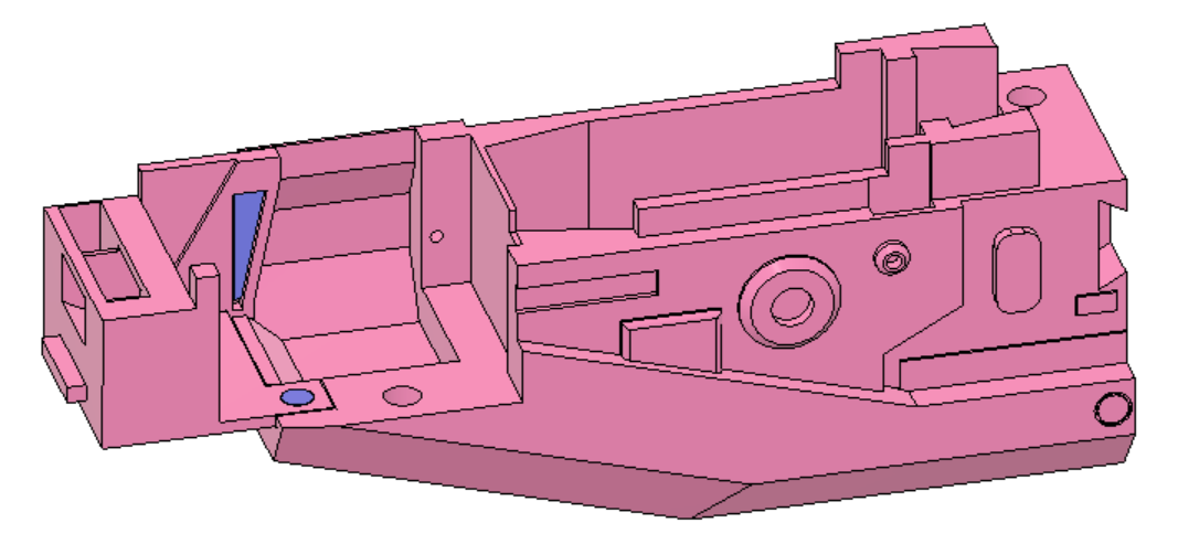
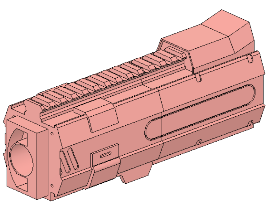
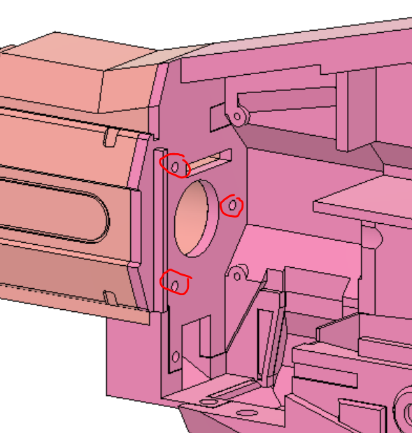
Depicted: Magwell, Insert
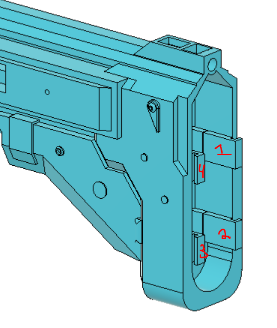
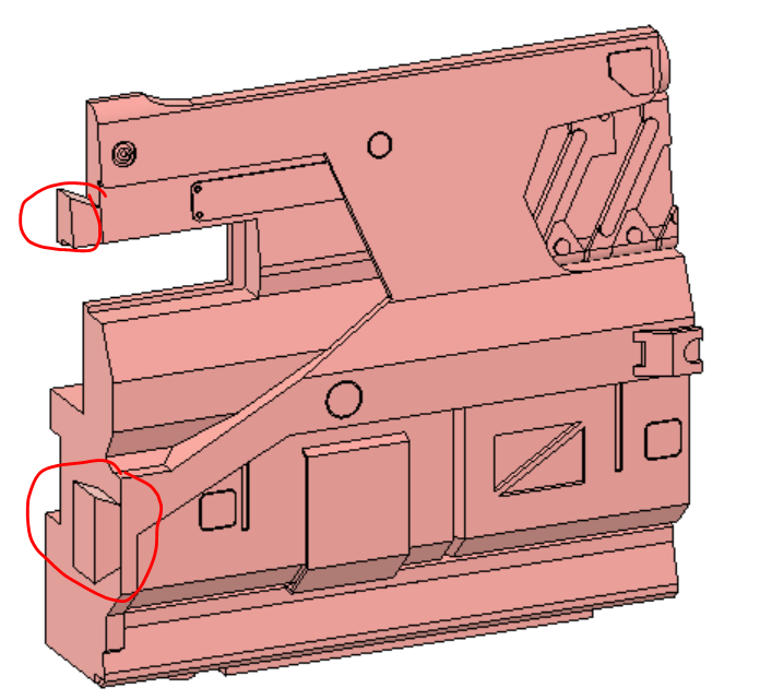
Depicted: 2X Button, 4X Slot, Button Mount, Buttstock, Fin, Left & Right Panel, Stock Main
The part circled in red is the Left Panel, and uses a thin surface for bridging in two areas near each button.
Now, if like me you are impatient and like to assmeble as you print, I suggest you begin by printing all the parts in the Body and Magwell folders. These two folders will make up about 60-70% of your time building Shadow Price since they have a relatively complex assembly that keeps the blaster robust and secure. I highly suggest you use some form of solvent weld for this blaster instead of an epoxy or superglue, as there are some areas that can take a lot of stress during a fall, and its better to be too secure rather than not. For PLA I suggest Weldon 16, for PetG or similar Pet filaments I suggest Weldon 3 or 4 (4 is just more viscous, same formula), and for ABS obviously any form of acetone.
One cool thing with Weldon 3 or 4 is that it also bonds styrene plastic, so if any part warps (like the Flywheel Cover) you can glue on styrene and it should be super easy to shape and fill gaps. Another good thing about specifically Weldon 3 is it is water thin, so you can use a small spray bottle head (make sure it doesnt disolve in the solvent!) or a brush to cover areas that seem to be cracking. This bonds the layers together like annealing and will make the area stronger (if you can, do this along the top angle of the Cage Mount). You can probably tell at this point that I printed mine in PetG.
Ok, suggestions over, lets start assembling:
- Screw into place and glue down Tail Dovetail into tail
- Screw into place and glue Insert into Cage Mount
- Glue the Cage Mount, Archway, Solenoid Mount, and Tail together in a line. We will call this group the "upper reciever"
- Glue and snap the Magwell and Battery Tray Latch together by aligning the circular cutout and snapping in the triangular piece. If you are using a water thin solvent snap the parts together then put a bit of solvent in between the parts.
- Glue the Alignment Tab into the Magwell. It should be a tight fit.
- Place the Mag Release lever into the Mag tooth and slot both into the back of the Magwell. Make sure the the cutout part of the lever faces away from the magwell, the part of the tooth that sticks out is towards the bottom of the magwell, and that no glue gets on any of these parts.
These next two steps need to be done pretty quickly if you are not using a water thin solvent, so prepare everything before hand. If you are using a water thin solvent, just dont put any solvent in until after all the pieces are locked in place.
- Glue and slot Trigger Well Right into the back of the Magwell. This will lock in the magazine lever and tooth so it is critical you align those before gluing this piece on. This collection of pieces we will call the "lower reciever".
- Glue, slot, and screw the upper and lower reciever together. Make sure the Alignment Tab is pushed into the back and top of the slot in the Archway, the spike on the front of the Cage Mount is flush with the cut out in the Battery Tray Latch and the screw is in place, the L shaped extrusion is in the corner of the Trigger Well Right, and that the entire top surface of the lower reciever is flush with the bottom of the upper.
From here on the rest of the parts are mostly cosmetic, however they make up a lot of the length and weight of the blaster. Make sure they are securely glued and mounted in place or you might get cracks in the shell after painting.
- Glue and slot the Handle into the bottom of the Trigger Well Right. It should be a secure fit, just make sure you push it as far up as possible.
- Place the small extension spring on to the Magazine Release pin, and insert the pair into the Knuckle Duster. Make sure the spring sits flat on the inside of the Knuckle Duster. I also suggest you paint this component before you put it in since there is no way to get it out. (Optional: add a bit of craft foam to the front of the Magazine Release to make it more comfortable to hit with your middle finger)
- Slot the Knuckle Duster assembly into the bottom of the Trigger Well Right and the bottom of the Handle, and align the Magazine Release with the Mag Release Lever, making sure that the system is free to move.
- Screw the Knuckle Duster into the bottom of the Handle and glue the top of it into the bottom of the Trigger Well Right and the Magwell. Be careful not to get glue on the release system.
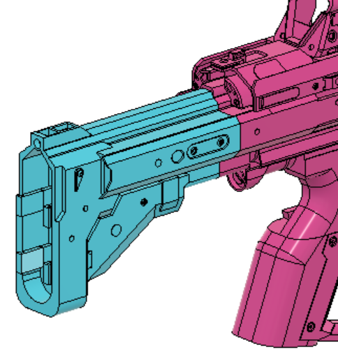
- Glue and slot the Stock onto the back of the Tail. Be sure to get good adhesion both inside and on the two flush surfaces.
- Glue and slot the four Slots into the back of the Stock. Be sure to press them in firmly or the buttplate might be wobbly.
- Glue and slot the Right Panel onto the right side of the Stock. Make sure to get good adhesion between the front of the panel and the Tail.
- Moving back to the front of the blaster, glue and slot the Top & Bottom Dovetails to the Cage Mount and Battery Tray Latch. Make sure they are flush with the exterior of the blaster.
- Glue and slot Barrel Middle and Barrel Back into place
- Glue, Slot, and Screw the Barrel assembly into place. Make sure it is flush against the Cage Mount both in the front and on the sides.
The next two steps are for one of the removeable covers, make sure not to glue it into the rest of the blaster.
- Glue and slot the top and bottom dovetails into the Solenoid Cover
- Glue and slot the Trigger Well Left into the bottom of the Solenoid cover. (Optional: glue the two at a slight inward angle so that when screwing into the blaster the panel will always fill the break at the top)
- Screw Picatiny Left & Right into the Flywheel Cover and Cage Mount, respectively.
- Slot and Glue Grill left & right into the solenoid panel assembly and Solenoid Mount, respectively.
- Slot and Glue the three Barrel Tips together.
Now other than removeable components (Which are screw in) the blaster is fully assembled. I suggest that you dont glue the barrel tip assembly into the Barrrel End because its prone to breaking, and make sure that at no point do you glue the Flywheel Cover, Barrel Front, Buttstock, and the Solenoid Cover/Trigger Well Right assembly to the rest of the blaster or you will be unable to insert the internals.
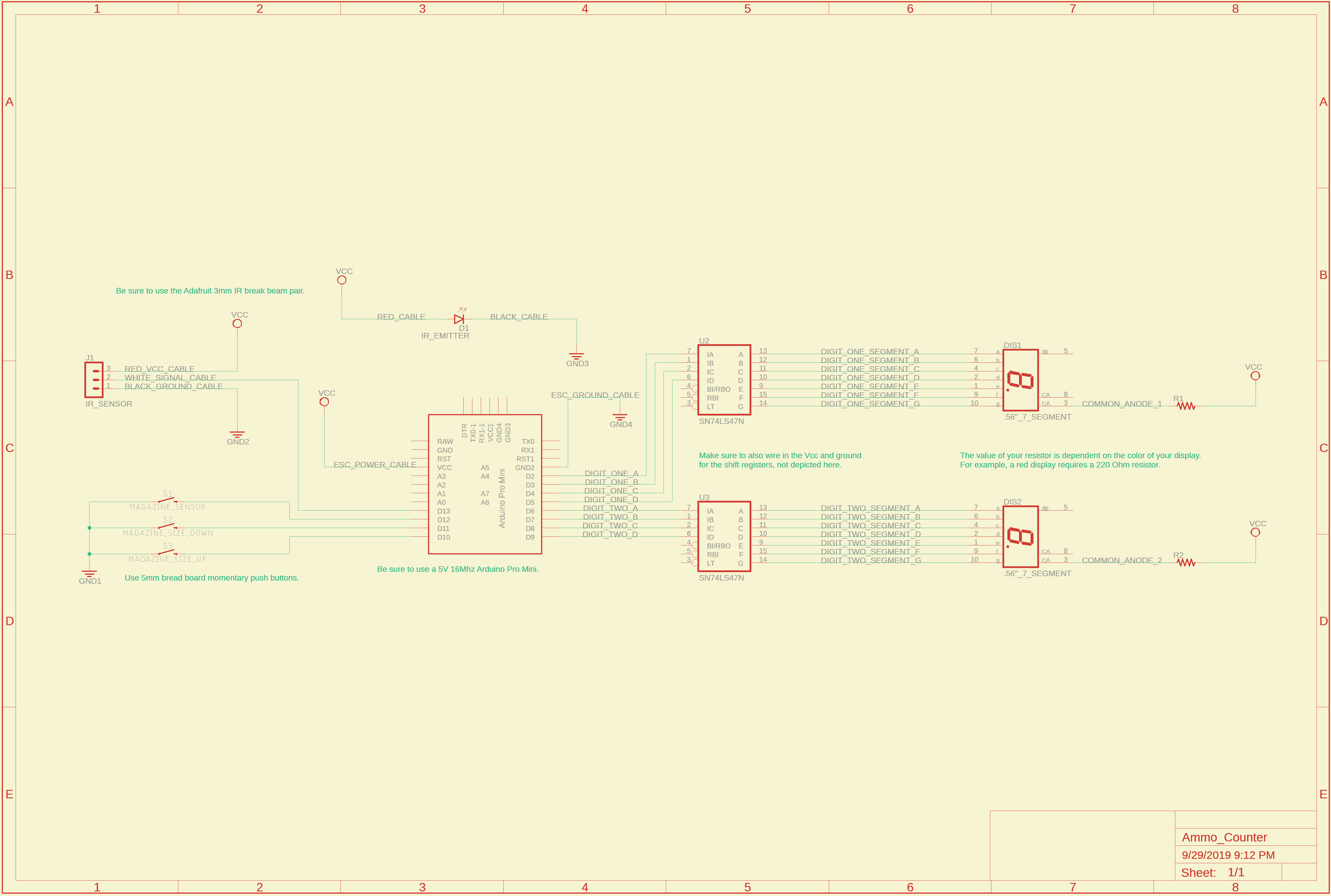
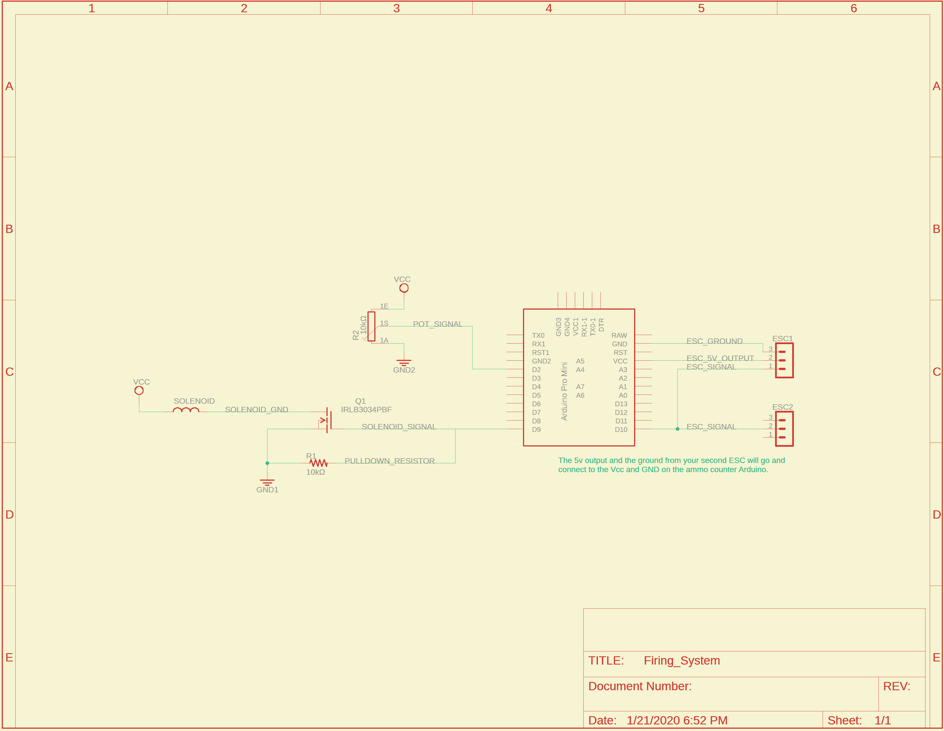
The blaster can be broken up into two circuits controlled by each of the Arduino Pro Minis and powered by each BEC output.
This is the diagram for the ammo counter
And this for the firing system
2Xkey file was added into the barrel folder. Two of them should be printed along the longest dimention and glued together. Will requre a little less sanding than the regular key, but it will still be a tight fit.
Swapped Left Panel and Stock Main in the stock folder for new versions that make use of a screw and bridging characteristics. No changes to printing orientation. Added another screw in the parts list.
Made changes to a majority of body components to improve aesthetics and to remove remnant geometry from older versions.
Major changes include a block to better attach the Handle to the Trigger Well Right, combining the Solenoid Mount and Top Picatiny to prevent cracking in both parts (as observed in my personal print), and adding a 1 deg angle to the connection between the Trigger Well Left and Solenoid Cover to close shell gaps.
Began to strenghten area around mag release by increasing contact between the Magwell and Knuckle Duster, however no changes have been made to the Magwell so currently the blaster is non printable.
Updated printing orientation photos and removed assembly step 16 pertaining to the Top Picatiny.
Broke down Barrel Main into two components, Barrel Back and Barrel Middle.
Replaced Barrel end with Barrel Front, now with the new attachment lugs and optimised for bridging.
Filled in gaps between Tail, Solenoid Mount, Solenoid Cover, Trigger Well Right, Magwell, Cage Mount, Flywheel Cover and Archway.
Cut out space in Magwell for the new Knuckle duster, now making the blaster printable again.
Cut a hole in the top of Cage Mount.
- Created two new parts, Tail Dovetail and Insert.
- Tail Dovetial holds Solenoid Cover from the back and hopefully reduce flexing on Solenoid Mount.
- Insert goes inside of Cage Mount and will hopefully reduce the cracking that occurs in that area.
- Parts list updated to reflect four screws that hold the pieces in place.
Increased Insert tolerances.
Added fillets to the picatiny on Solenoid Mount to reduce the need for supports.
Updated printing and assembly photos to reflect geometry changes.
NOTE: Since many changes had no effect on assembly, not all photos were switched out, so go by description and use the photos as refrence.
Multiple minor geometry changes as I print another shadow price and issues arise.
- Pushed back dovetail and increased angle on Handle.
- New female side of dovetail on Trigger Well Left.
- Added screwport between Trigger Well Right and Left.
- Added reinfocement bar to Solenoid Cover to prevent cracking on small upper area.
- Removed extraneous walls in Archway to help with aethetics.
- Minor wall adjustments on Solenoid Mount so it meshes better with Archway and requires less support.
Updated Parts list with extra screw.
Redesigned all dovetails connecting the removeable handle cover from the blaster.
- Added new part, Tail Decoration, to prevent the need for a large support tower.
- Added a Dovetail to the side and back of Magwell and Archway.
- New locations for two of the screws, moved from Trigger Well Left onto Solenoid Cover.
- Removed Top and Bottom Dovetails as they are now extraneous parts.
Created new set of combined parts for larger printers (150mm+ in X or Y).
- Added new parts Trigger Well Left Combined, Trigger Well Right Combined, Handle Combined.
- Moved geometry constraining the magazine release system onto the trigger well pair, should now allow for removeable components.
No changes to assembly order but some steps need to be removed due to dovetail changes.
Reinforced Magwell and surrounding parts
- Added bridge support to Magwell dovetail.
- Thickened wall on Magwell under the cage.
- Made the anchor for Battery Tray Latch larger.
- Removed extra features on inside of Cage Mount, added chamfers to reduce supports and increase strength, added extra screwport at the top of the Back Barrel connection, thickened walls and added bridge supports.
Minor changes to Solenoid Mount and Cover to reduce required support.
Removed the original trigger well files as the new dovetail geometry was not reflected in their design and made them redundant. The Knuckle Duster does not reflect the changes on the Trigger Well Combined files, so for now only use Handle Combined.
Cleaned up extraneous surfaces on stock main.
Dropped height of Battery Tray so top is planar, makes printing easier.
Increased wall length of Barrel Middle and Front to match Battery Tray.