- Introduction
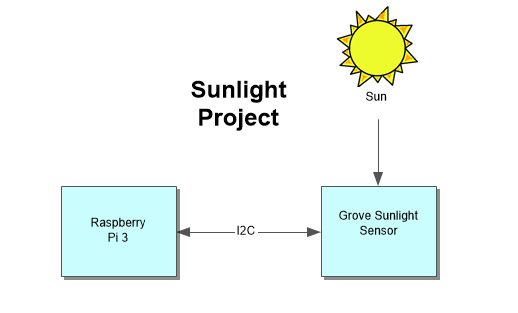
- System Diagram
- Bill of Materials/Budget
- Time Commitment
- Mechanical Assembly
- Soldering
- Power up
- Unit Testing
- Production Testing
- Reproducible?
For my Hardware Project I decided to build with the sunlight sensor. The sunlight sensor will measures sunlight and break the sunlight down into three components (Ultraviolet light, visible light (in Lumens) and infrared light (in Lumens). This will allow to monitor the sunlight intensity, IR intensity and UV intensity.
The sunlight sensor uses SI1145 which will measure the total visible light (in Lumens), infrared light (in Lumens) and UV light (UV index). This can be useful because with this sensor you can detect how much visible light and infrared light is emitted by the sunlight. With the value from uv light you can use the data to find out the UV index and know how much UV light is emitting from the sunlight.
The materials needed to build the sunlight sensor project is Raspberry Pi 3, Grove I2C Sunlight Sensor / UV / IR and Pi2Grover - Grove Connector Interface for the Raspberry Pi. The parts can be bought from amazon or switchdoc labs. I bought my parts from amazon.
- Raspberry Pi 3 (CanaKit Starter Kit):
- Amazon CAD $99.99
- Grove I2C Sunlight Sensor / UV / IR:
- Amazon CAD $21.64
- SwitchDoc Labs US $13.95
- Pi2Grover - Grove Connector Interface for the Raspberry Pi:
- Amazon CAD $31.17
- SwitchDoc Labs US $19.95
At the time when I bought the materials, the raspberry pie was $112.99, Sunlight sensor was $36.64 and Connector interface for the raspberry pi was $36.17, plus the shipping $15.41. The total cost for buying the materials was $201.21.
This project can be completed in a couple of days if you followed the mechanical assembly and the diagram. From my experience it took me 1 to 2 weeks to complete the build. I first had to order the materials which will take around a week to arrive. Once you receive the materials, I set up the raspberry pi which took around 3 hours. Connection the parts to the raspberry pi took around 30-60 minutes. And then setting up the code on the raspberry pi and testing the code took around a 1 hour.
Overall, I think the needed time to complete this build should be around 3 hours daily for 2-3 days.
- First, power of the Raspberry Pi
- Next, will be connecting the connector interface to the Raspberry pi 3. While holding the connector interface, align the pins on the Raspberry Pi 3 GPIO header and carefully push down the connector interface board on to the Raspberry Pi 3 board.
- Then, plug in a Grove Cable that comes with the Grove Sunlight sensor to the sunlight sensor and plug the other end of the cable to any of the I2C plugs on the connector interface.
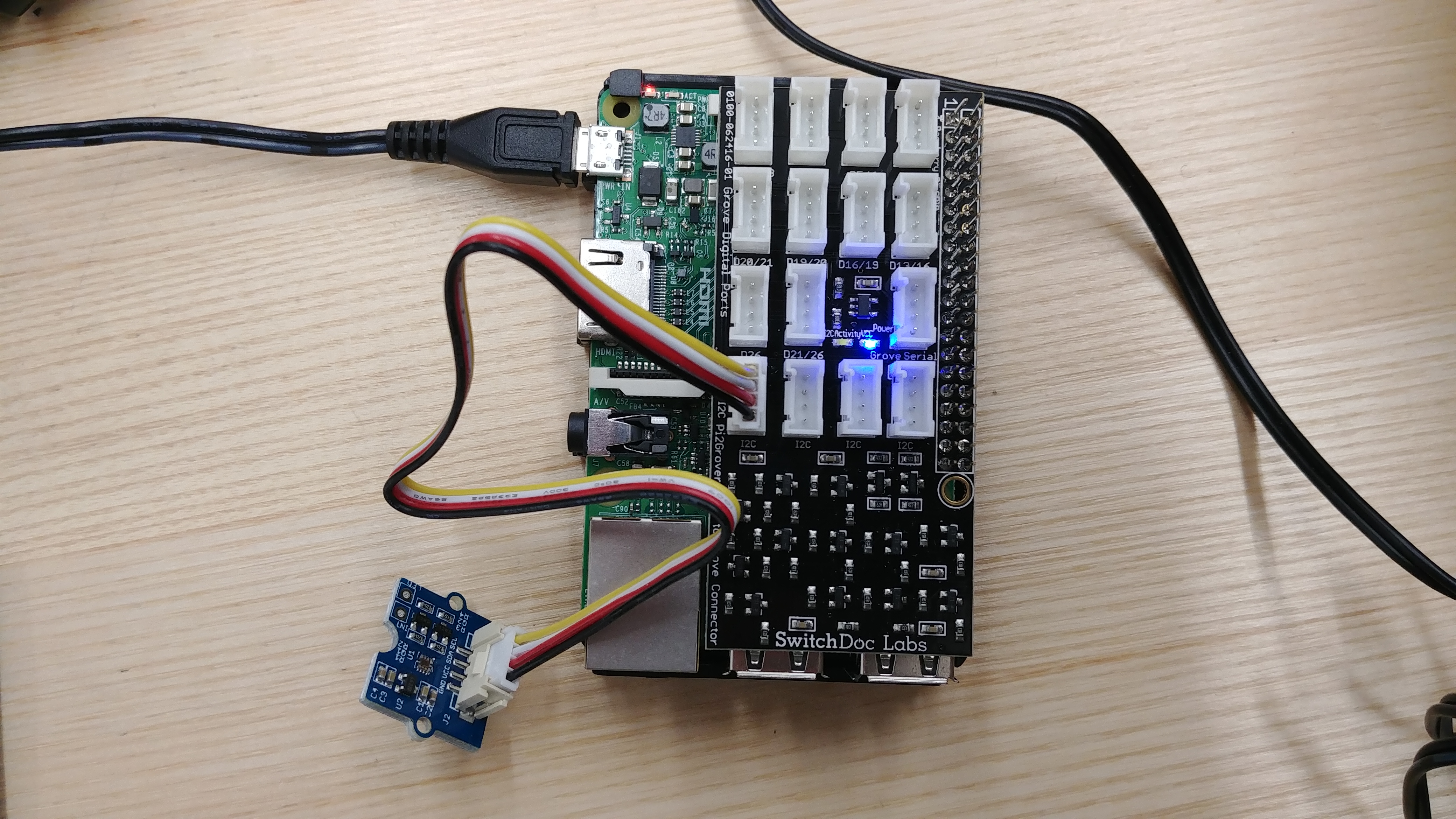
- Once everything is connected, you can power up the Raspberry Pi. If you see a blue LED on the connector interface it shows that the connector interface is connected.
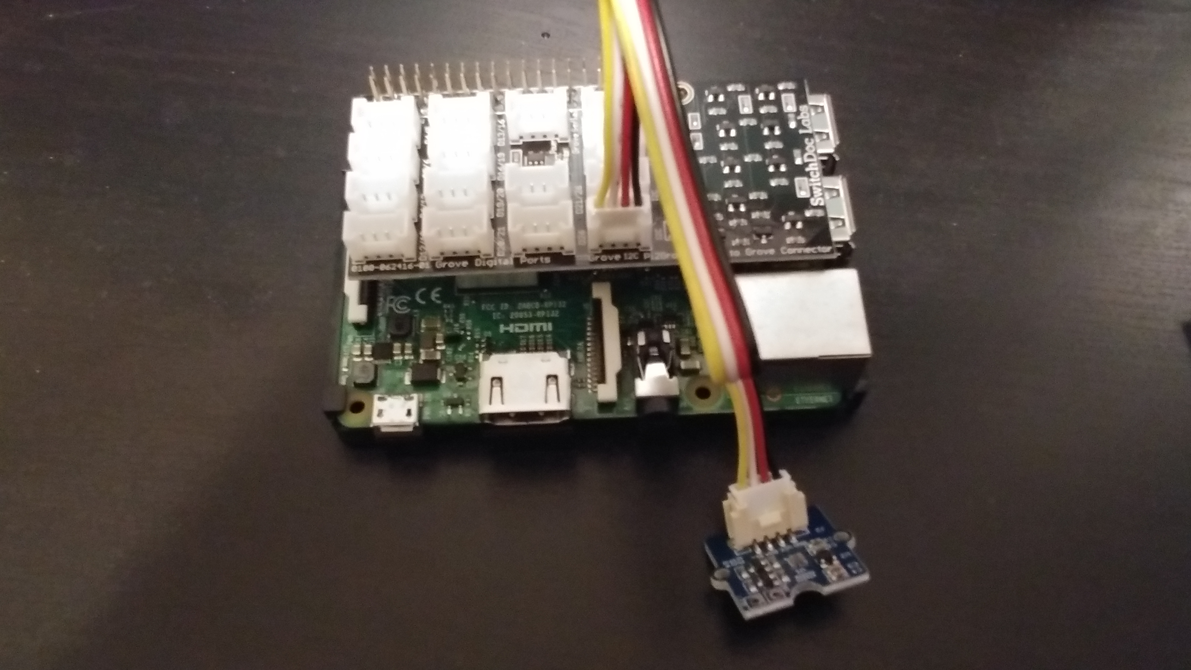
Below is the outcome after you connect the parts to the raspberry pi.
There was no soldering required with the sunlight sensor. The sunlight sensor is connected by using the Grove Cable to the connector interface on the raspberry pi.
Before power up the Raspberry pi, check the micro SD card to see if it has the contents of NOOBS operation system installer which contains Raspbian. If not, you can download, unzip and copy the folder contents of NOOBS into the root directory of the micro SD card. On the first boot you will be prompted to install the operating system and configure the wifi setting. Once the raspberry pi is done installing the operating system. The first thing is to enable I2C because by default it is not enable. I2C bus allows the devices like the sunlight sensor to be connected and detected on to the Raspberry Pi. To enable I2C: from the Start Menu -> Preferences -> Raspberry Pi configuration -> Interface set I2C to Enabled.
Next on the terminal type the following command to check that you have i2c-tools utility installed.
sudo apt-get install -y python-smbus
sudo apt-get install -y i2c-tools
To check if the raspberry pi is detecting the sunlight sensor: Open the terminal and type the command
sudo i2cdetect -y 1
If you see this, it means that the raspberry pi is detecting the sunlight sensor and you connected the sensor to the raspberry pi correctly.
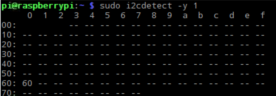
0x60 is the Sunlight Sensor.
The next step is to install the APscheduler. The Advanced Python Scheduler is a task scheduler that lets you schedule functions to be executed at times of your choosing.
On the terminal type the follow command to install APscheduler.
Sudo pip install setuptools –upgrade
Sudo pip install apscheduler
Next is to install the software and download the code to run the sunlight sensor You can download the files required to run the sunlight sensor here.
Unzip the file and save it on the root directory on your raspberry pi.
On the terminal type the following command:
cd firmware/Adafruit_Python_PureIO
sudo python setup.py install
To run the code, enter the follow command:
cd firmware
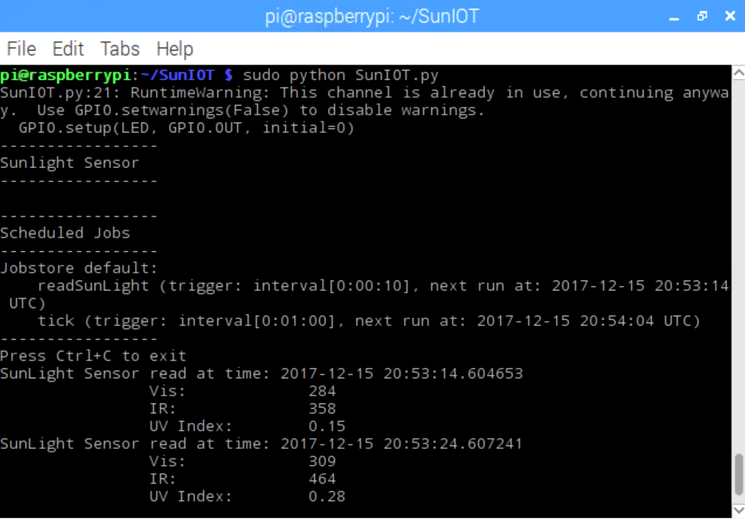
python SunIOT.py
The program will execute.
Once the program successfully executes the output will display the Vis (visible light), IR (infrared light) and UV Index (UV-Light) from the sunlight sensor.
Pictures of the sunlight sensor project and the code running:
By following this build instruction, I believe you will be able to reproduce the sunlight sensor project. I have provided in my GitHub, budget, instruction on how to build and setup the code.