This project aims to showcase how a simple CNC router can be built using a microcontroller and serial communication instead of using the old printer port parallel port for real-time stepping. In this readme, I will first introduce the fundamentals of CNC systems and their traditional approach of parallel stepping. Then we will discuss the drawbacks of the traditional setup and how this project provides an alternative solution.
A CNC (Computer Numeric Control) machine is a type of machine that can move according to absolute or incremental coordinates and perform certain actions on the given location or on-route between two sets of coordinates. CNC machines are used in various applications, including CNC routers, 3D printers, laser cutters, and more.
The coordinate instructions for CNC systems are typically stored in a file called G-code, and the main control logic is responsible for converting these coordinates to machine instructions. In simple CNC systems, the main control logic may be software-based, and the hardware side of the CNC machine does not have a buffer to store the whole G-code. As a result, these systems rely on external devices that can store, translate, and communicate the content of the G-code to the logical CNC controller.
In many cases, the G-code is stored on a PC and loaded through a trajectory planner. The trajectory planner has information about the machine's physical setup, steps/unit, acceleration curves, input/output devices, etc. It also keeps track of current axes locations and I/O states. The motors used in CNC systems are typically stepper motors, which move one step at a time in the desired rotary direction.
In the traditional approach of CNC systems, the motion instructions are communicated through a parallel port (such as the old printer port) in real-time. Typically, there will be three pins per axis: Step, Direction, Enable. These pins are switched according to the desired motion. For example, for the X-axis, the direction pin can be set to positive, and then 200 steps can be sent out on the step pin over the course of one second. This means that a typical stepper motor will move one whole rotation in one second.
In extended setups, the stepper motor resolution can also be controlled by additional pins, in order to subdivide each step by a certain factor. In practice, this means that the coils in the motor will maintain a proportional current load for each step in order to hold the motor-core fixed in magnetic middle-stages. Step, direction, enable, (and resolution), logical values are sent to a motorcontroller. This is typically an integrated circuit, which creates high-low patterns to match how the motor coils must be switched respectively to perform a step. Between the logical motorcontroller and the motor itself, is a motor current driver, which in essence is a simple transistor (for example, a MOSFET), that lets current flow from a power source and through the motor coils according to the received switch pattern.
The traditional parallel stepping approach has several drawbacks, including:
- The parallel communication is done through the printer port, which is an old technology and not available on most modern PCs and laptops.
- The parallel port is limited by its bandwidth. On higher resolution machines, many steps must be executed per second, and the tick rate of the port may not be high enough to hold all the required steps.
- The parallel port is highly susceptible to noise, and there is no acknowledgement of sent/received information. The logical state of pins in the parallel port is fragile. Therefore, noise can induce unwanted steps or cause steps to be lost.
- When stepping at higher speeds, the logical readout is being smoothed, which can cause logical states to become blurred and unreadable by the receiving motorcontroller.
This project showcases a CNC system with an alternative communication form between the PC and the motion controller. Instead of using the printer port, serial communication is used between the PC and the control logic. This approach replaces real-time stepping with one-line-at-a-time execution.
The system components for this CNC system are:
- PC
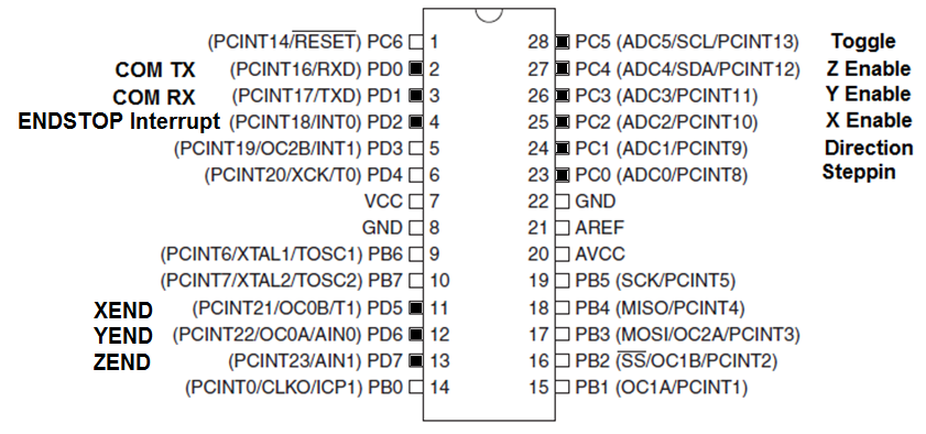
- AtMega328PU MCU (Microcontroller Unit) - the main control logic
- Motorcontroller (L297)
- Motor Driver (L298)
- Stepper Motor
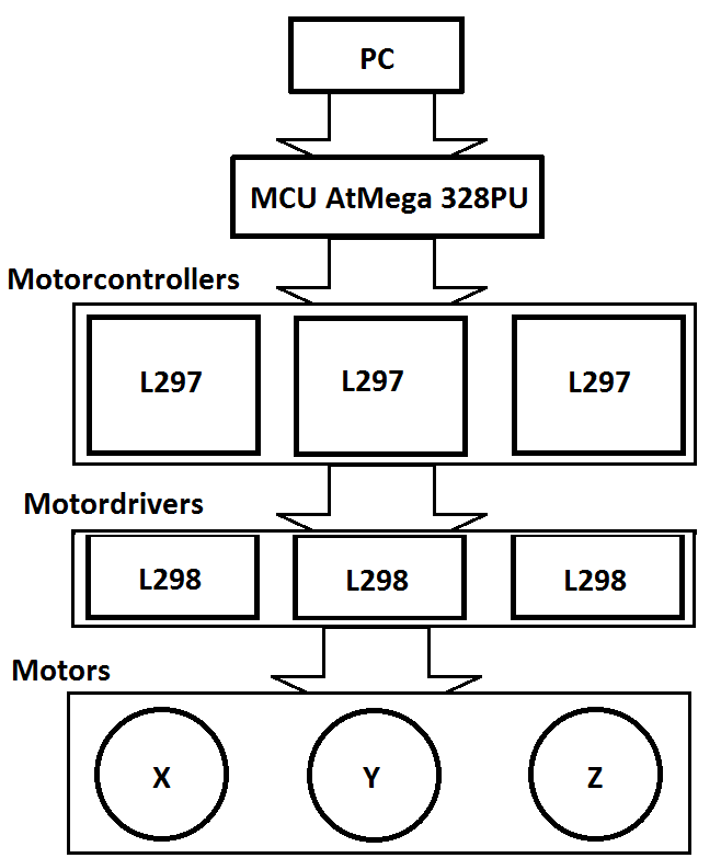
The project involves adding a microcontroller (AtMega328PU) between the PC and the motor controllers to control the stepper motors. The PC acts as the trajectory planner, where the gcode is loaded, and information on motor steps/unit and current positions is stored. When a line of gcode is read, the PC converts the coordinates into machine instructions (step, direction, enable, spindle) for controlling the stepper motors. This information is then encoded into two bytes and sent serially to the AtMega328PU MCU via the PC's RS232 interface. The information is encoded as shown below:
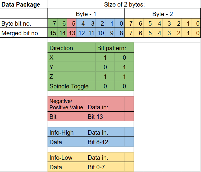
Once the data package is received, the AtMega328PU segregates the bits relevant to each control function and switches the output pins accordingly to execute a step-routine. The MCU uses information on motor pin mapping and sensor inputs to control the motion of the stepper motors by switching output pins connected to the L297 motor controllers.
The L297 motor controller generates high-low patterns to switch the motor coils for each step, and the L298 motor driver allows current to flow through the motor coils. By working together, these components ensure precise and accurate control over the motion of the stepper motors.
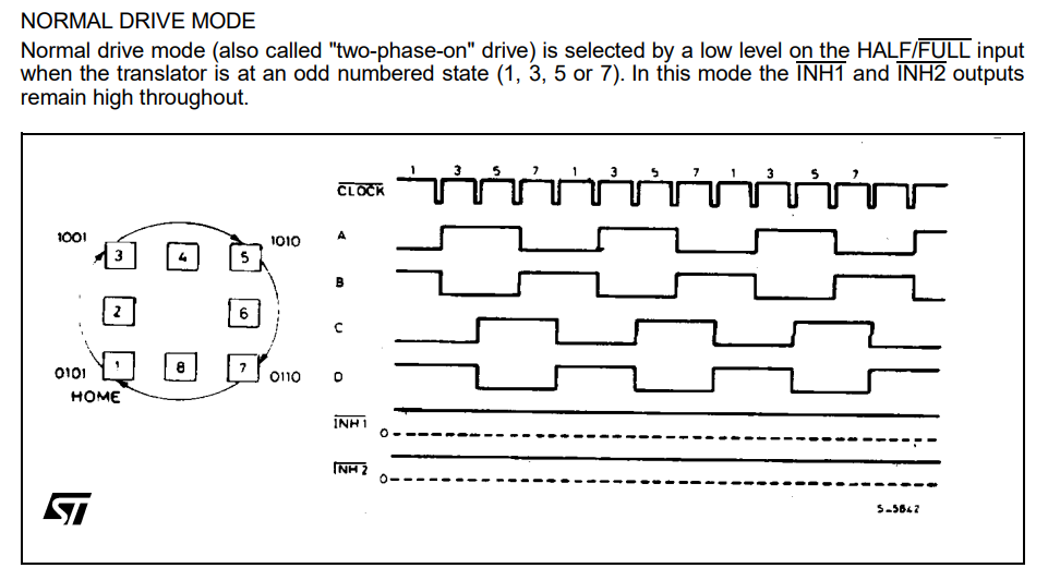
(Source: https://www.st.com/en/motor-drivers/l297.html)
The approach used in this project has several benefits over traditional parallel stepping, including:
- Serial communication is more readily available on modern PCs and laptops.
- Serial communication has higher bandwidth than the parallel printer port, allowing for more steps to be executed per second on higher resolution machines.
- Serial communication is less susceptible to noise, and the use of acknowledgement and error-checking protocols ensures that the logical state of the system is more robust.
- One-line-at-a-time execution allows for smoother motion per axis and reduces the likelihood of missed steps or unwanted steps.
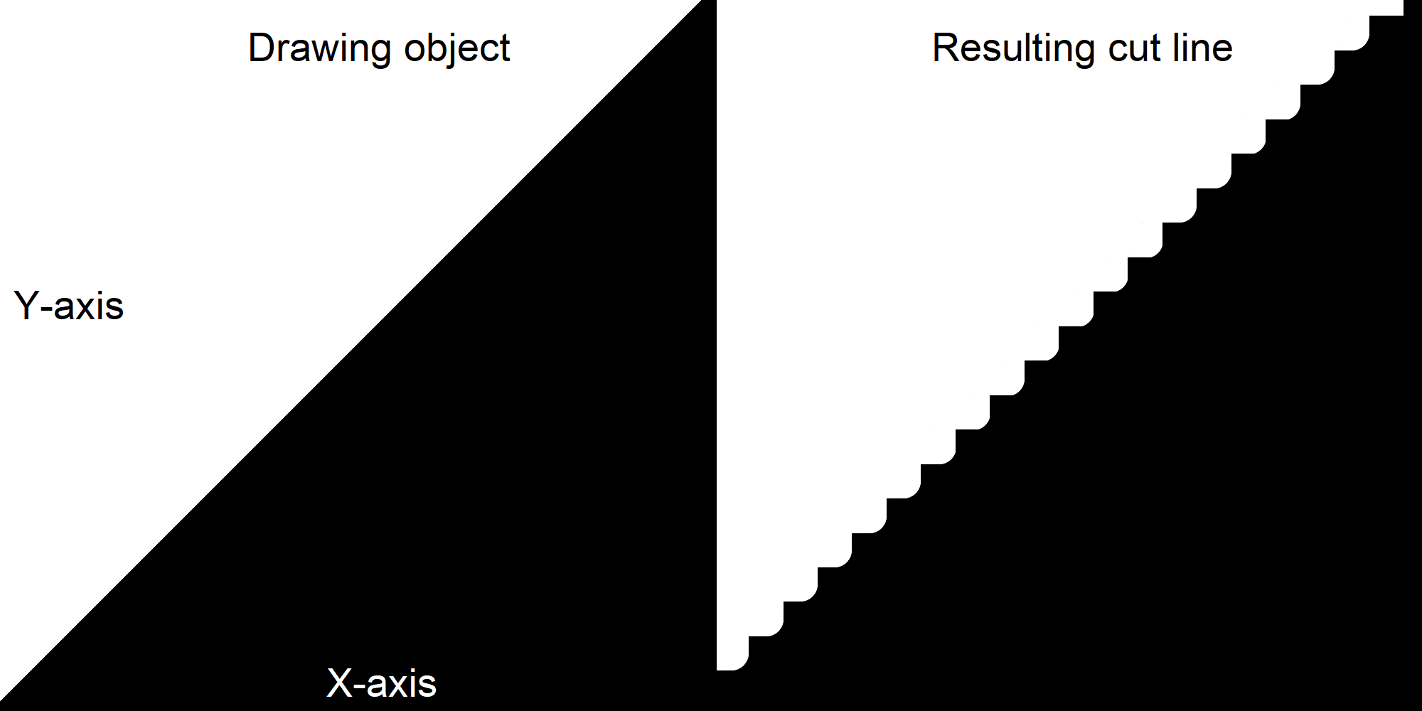
One limitation of this approach is that the AtMega328PU MCU has limited output pins. Therefore, only one step pin and one direction pin can be used, and an enable pin for each axis (x, y, z) is used to direct steps to the relevant motor. This means that only one axis can be stepped at a time, and the active state of the enable pins determines which motor is currently being stepped on. Consequently, cut-lines that require more than one axis to draw will be interpolated in a staircase pattern based on the step/unit resolution, which may result in a loss of precision in certain cutting or drawing operations that require smooth, continuous motion across multiple axes.
The Serial-CNC-Stepper project showcases how a simple CNC router can be built with an alternative communication form that replaces traditional parallel stepping with serial communication and one-line-at-a-time execution. This approach offers several benefits over traditional parallel stepping, including greater availability, higher bandwidth, and greater robustness against noise and errors.
To get started with this project, you will need the following:
- 1 PC
- 1 USB to Serial RS323 adapter (if the PC has no serial port)
- 1 AtMega328PU MCU
- 3 Motorcontrollers (L297)
- 3 Motor Drivers (L298)
- 3 Bipolar Stepper Motor
- Breakout board and Wires
- Optional: 1 physical 3-axis CNC for the motors to control
- AVR Studio (For dependencies and building the code)
- <avr/interrupt.h>
- <util/delay.h>
- "uart.h"
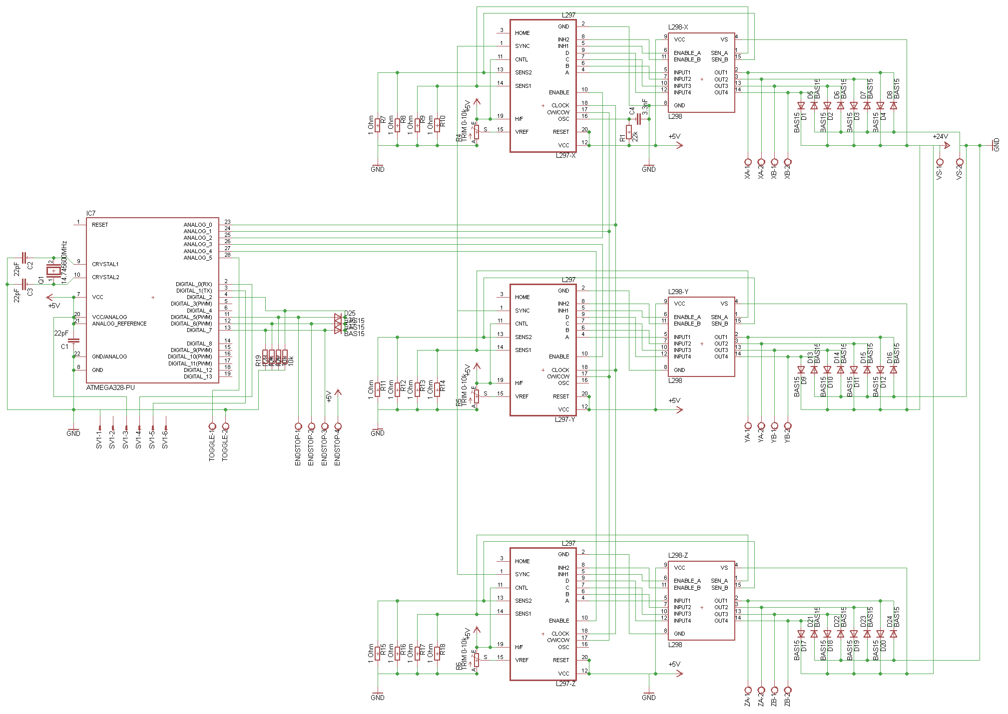
The components are wired as following (click to enlarge):
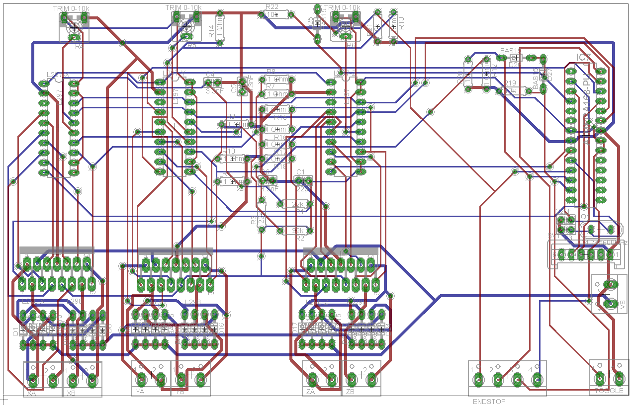
Print Board Circuit Layout top and bottom (click to enlarge):
Do not attempt to use this project for controlling live CNC machinery. It is meant for demonstration and learning purposes only.