Home
In order to keep a high longevity of the battery we must take care of how we charge and discharge it. Projects being powered by a 7.4 Volt lithium polymer battery (Conrad Electronic: Conrad energy LiPo ET Flugakku 7.4 V / 1000 mAh), which are built as a pack with two 3.2 Volt cells, shall use this component to avoid damage to the battery.
The charging task we delegate to a specialized LiPo balancer charger device (Conrad Electronic: VOLTCRAFT (202BC) 230 V Ladegerät), which is designed to fulfill the specific requirements.
The discharge part is something we have to take care of. We must ensure that the battery voltage does not fall below 6 Volts. In order to measure the battery voltage we use a controller analog input. If the voltage falls below a warning threshold level (6.5 V), a power alert shall be displayed. If the voltage drops below the stop threshold (6.3 V), the actors will not be allowed to run anymore. If the level falls down below 6.1 V, the microcontroller has to put into power down mode.
The following voltage limits apply when using a 7.4 V LiPo battery (battery pack built with 3.2V cells in series):
| Battery Charge State | Symbol | [V] |
|---|---|---|
| fully charged | VBatMax | 8.4 |
| discharged | VBatMin | 6.0 |
| Symbol | [V] | consequent action |
|---|---|---|
| BATT_WARN_THRSHD | 6.5 | power alert on display |
| BATT_STOP_THRSHD | 6.3 | inhibit actors operation and switch display backlight off |
| BATT_SHUT_THRSHD | 6.1 | controller power down |
The Arduino analog digital converter has an input voltage range from 0 up to 5 Volts (by default). Since VBatMax = 8.4 V being far higher than 5 Volts, the measurement signal has to be converted by a voltage divider.
We choose a divisor of around 2, so we can measure voltages up to around 10 Volts.
The converter's maximum output voltage shall not exceed 5.1 Volts.
The measurement signal at the output shall be noise reduced.
- avoid to draw any current out of the battery unless the charging level is over the minimal threshold
- get warned or take appropriate measures if certain thresholds are underrun by the battery voltage
- Threshold Levels and their appropriate measures:
- BATT_WARN_THRSHD, 6.5V, power alert on display
- BATT_STOP_THRSHD, 6.3V, inhibit motor operation and switch display backlight off
- BATT_SHUT_THRSHD, 6.1V, controller power down
- Notifications shall be sent out on each threshold the battery voltage is falling below
- the battery status shall be readable:
- the current voltage
- if the voltage is below the warning or the stop threshold level
- optional: battery mileage
- optional: battery charge cycles
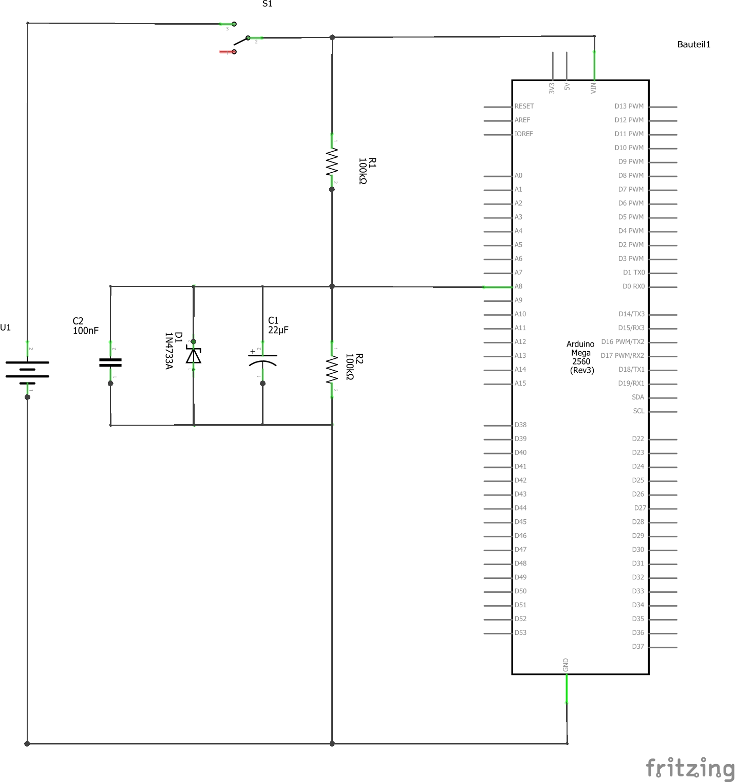
The voltage divider resistors having 100 kΩ each provide a high impedance circuit. The advantage of this is low power consumption and protection against high current through the analog input in case of overvoltage.
The disadvantage of this high impedance design is the high noise sensitivity. To cope with this, the 100 nF capacitor is in place.
The 5.1 V Zener Diode ensures that the Arduino analog input will not go beyond 5.1 Volts.
The 10 μF capacitor filters out ripple generated by motor operation.
Since the resistors will never be exactly the same, and their ratio will be different on each single HW, we have to determine the ratio constant by measuring the signal conversion circuit on each instance.
The individual ratio values then have to be stored in a non-volatile memory as a part of an inventory management storage.
| Symbol | Value | Unit | Remark |
|---|---|---|---|
| VADCFullRange | 5 | [V] | |
| NADCFullRange | 1023 | [1] | |
| BattVoltageSenseFactor | ~ 2.0 | [1] | Inventory Management Data, individual constant, different for each instance |
| rawBattVoltage | [1] | number {0..NADCFullRange}, dependent to currrent voltage on analog input | |
| battVoltage | [V] | calculated voltage |
battVoltage = rawBattVoltage * BattVoltageSenseFactor * ( VADCFullRange / (NADCFullRange + 1) )
- Events
- Power up event (on startup, 0.5s delay after application started running); no battery voltage supervision shall be performed, unless this event has triggered
- Periodically poll the voltage level, polling interval: 1 s
- Change of the individual voltage sense factor in the inventory management data
- optional: Power down interrupt
- Processing
- compare read voltage levels against the threshold values on each poll, consider a hysteresis of 0.2 V to recover from a certain state
- perform the signal conversion
- take into account the individual voltage sense factor stored in the inventory management
- avoid reading from the inventory management data (EEPROM) on every signal conversion, read it from a cached value, rationale: reading from EEPROM has a high timing cost, since the EEPROM storage is a slow memory device Page 52 of 59
- store the last read value in order to detect changes, and optionally: to report trends
- optional: recognize and count any battery charge process finished (after power up), based on inventory management data
- Actions
- Notification when the battery voltage value falls below any of the three threshold values
- read the current individual voltage sense factor from the inventory management data on
- power up (on startup)
- on change notification
- optional: store the last battery voltage value in the inventory management data on power down
- optional: read the last battery voltage value from the inventory management data on power up
- Status Information
- the current battery voltage level shall be readable
- the voltage level is good (above the BATT_WARN_THRSHD + hysteresis)
- the voltage level reached warning state (below BATT_WARN_THRSHD)
- the voltage level reached stop state (below BATT_STOP_THRSHD)
- the voltage level reached shutdown state (below BATT_SHUT_THRSHD)
- optional: present the charging cycles and the mileage of the battery
The following class diagram shows the Battery component integration into Lintilla.Embedded application.
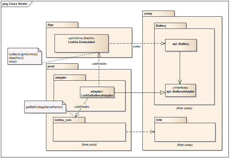
Mainly the application (Sketch) calls the API functions of the Battery component, either to send events or to get status information.
The Battery component on the other side sends out some notification callbacks through the adapter. The specific adapter method implementations by LintillaBatteryAdapter will then call the IVM or some global functions implemented by the sketch.
The proposed internal structure is shown by the following class diagram:
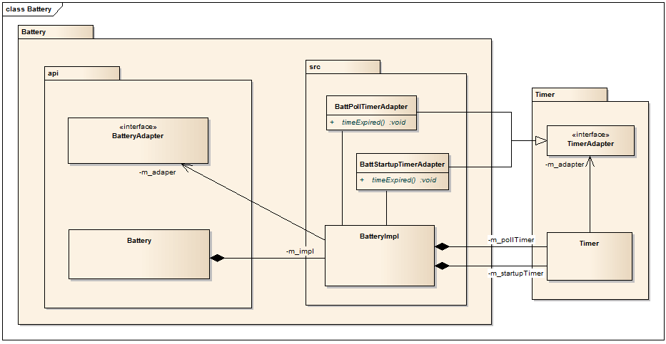
Implement the classes based on this draft and based on the specifications above.
The following class descriptions list the responsibilities and collaborations of the classes to be implemented.
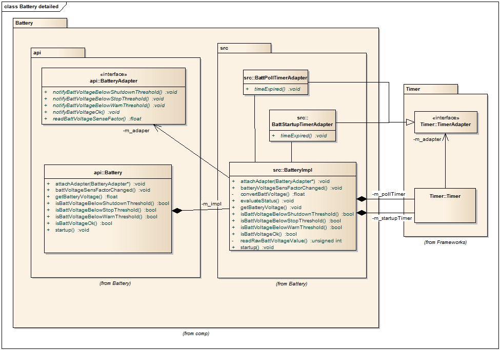
- is the API class for the component
- creates an object of the type BatteryImpl
- allows to attach an application specific adapter object implementing the BatteryAdapter interface
- defines the event methods
- startup
- voltage sense factor changed
- defines the status request methods
- get battery voltage
- is below threshold xy
- is battery ok
- all the methods are directly 'wired' with the corresponding methods of the BatteryImpl class
- knows the object of an application specific BatteryAdapter implementation, if attached
- creates the poll timer, recurring, interval 1s
- creates the startup timer, non-recurring, 500ms
- defines BattPollTimerAdapter and BattStartupTimerAdapter classes inline
- injects an anonymous instance of BattPollTimerAdapter into poll timer
- injects an anonymous instance of BattStartupTimerAdapter into startup timer
- knows all threshold values, they will be initialized with default constants
- stores the voltage sense factor (cached from inventory management data)
- implements the event and status request methods, same signatures as defined in Battery API class
- performs battery status evaluation
- on every poll timer event
- do the signal conversion
- according to the thresholds
- the polling timer is started as soon as the startup timer has expired
- the startup timer will be started on the startup event
- is a callback interface, all methods are pure virtual
- provides battery status notifications, according the thresholds
- battery good
- battery voltage below xy threshold
- provides voltage sense factor inventory management read request
The following more detailed class diagram gives you some hints for a possible implementation: