
This Project is done by Eng. Abduallah Damash, and assigned to me by Asst. Prof. Dr. Canras Batunlu as part of EE302 (Feedback System) course.
If you have any issues or comments on the project, contact me on Linkedin (https://www.linkedin.com/in/engabduallah). I also provided all the files that I used in this project so that you can try it by yourself.
Insight about the project:
The aim of the project is to run an analytical simulation to decide what is the better approach for controlling the motor of drone wing. That is by designing three types of controllers for different speeds to decide which one will make the system more stable in term of the maximum overshot and settling time for all the speed. Also, the system will continue three main components which are the controller, the motor, and the negative unite feedback.
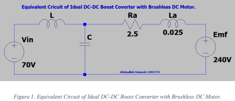
Motor Circuit Design:
in order to design a control system that contain a DC motor, controller for adjusting the speed of the motor, and a unity negative feedback, we can model the DC motor by using DC-DC boost converter that will switch when the controller need to adjust the speed.
Controller Parameters:
Let consider the transfer function of the PID, PD, and PI controllers in order to find the 𝐾𝑃,𝐾𝐼, 𝑎𝑛𝑑 𝐾𝐷 parameters in the closed loop system. In fact, these parameters can be found using Ziegler-Nichols Tuning Method.
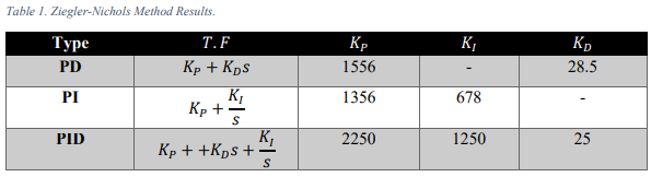
Notice that each type of controller has different gain parameters because they need to meet the requirement of maximum overshot to be less than 15% and settling time around 3 seconds.
MATLAB Circuit:
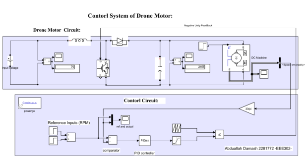
Simulation Results:
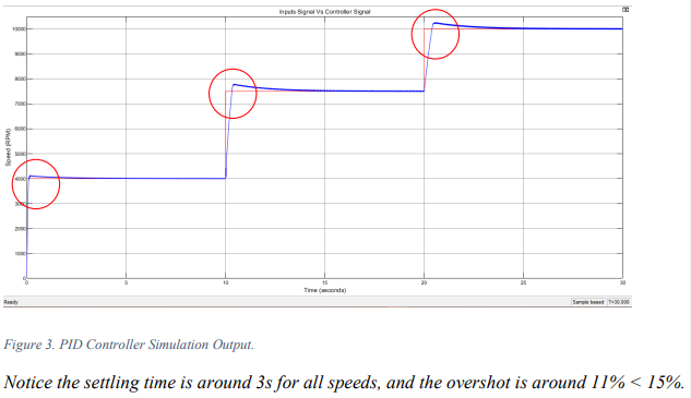
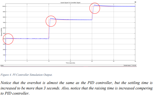
Now, in order to generate 3 different speeds, there are two step inputs that start at 4000 rpm, and then increased to 7500 rpm ending at 10000 rpm at each 10 second, so total simulation time is 30 seconds. Running the simulation with the values found in Table.1, it will be as following:
-PID Controller Simulation Output:
-PI Controller Simulation Output:
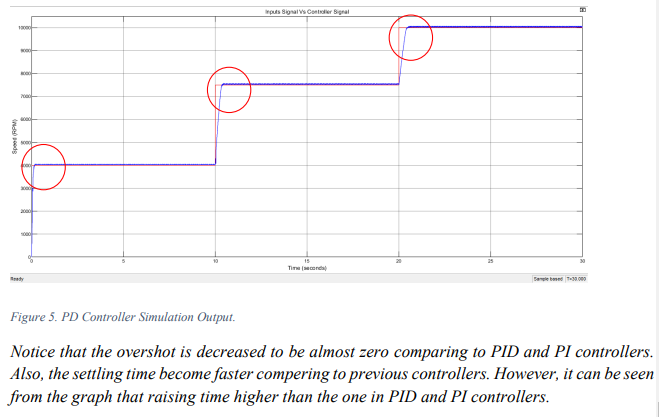
-PD Controller Simulation Output:
Conclusion:
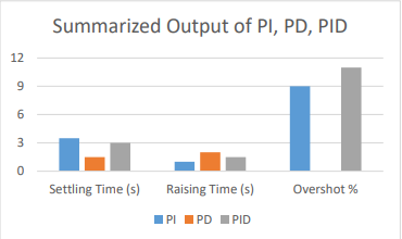
In the end, we can conclude that the best approach for designing an effective control system for the drone motor that is using PID controller because it meets the parameter of the overshot and settling time. However, using PD will be better in systems where we need to minimize the overshot of the system as shown in the graph. Also, PI optimizes the raising time compering to other ones so it can be used in systems where raising time is a critical parameter.
Each type of controller has its advantage and disadvantage and choosing which one is better depends on the different parameter in the system such as settling time, overshot, raising time.etc. That come from experience and observing different control systems in different application.
Enjoy it.
All rights saved, if you want to use any piece of the code, mentioning my name will be enough.