
This repository contains the code and 3D models required to build the TerRanger Smart Walking Stick, my dissertation project for the MSc Connected Environments course. The TerRanger system consists of 2 key components: the smart walking stick device and a mobile application that pairs with it using Bluetooth Low Energy (BLE). TerRanger uses two STMicroelectronics VL53L5CX tiny LiDAR sensors to map out the terrain below the hiking stick. This data is then translated into point-cloud form and visualized on the mobile application. TerRanger utilises the terrain surface data to estimate erosion along hiking paths, and is essentially a feasibility study to show that trail erosion monitoring can be semi-automated using embedded, low-cost technology.
You will need the following materials:
- A 3D printer (with nozzle size no larger than 0.4mm) & filament
- A UV printer (optional)
- An Arduino Nano BLE 33 Sense (rev1 was used in this build, but rev2 can probably also be used with some modifications)
- Protoboard or stripboard
- Electrical wire
- A capacitor (at least 33µF)
- A 10kΩ resistor
- A tactile button
- A 5V stepup converter/regulator (Pololu 5V S7V8F5)
- A LiPo charging module (Adafruit bq24074)
- A 2000mAh LiPo cell
- 2 x VL53L5CX LiDAR Time-of-Flight sensors
- A toggle switch
- 2x 4 pin JST-SH cables
- Assorted M2 screws and bolts
- Washers
- Pin headers and sockets
- Velcro strap
- A walking stick for hiking
- An Android smartphone
To construct the electronics, the protoboard/stripboard should first be cut to the dimensions 51mm x 62mm. Then, the circuit can be constructed using the following breadboard and schematic as a guide:

Fritzing breadboard diagram

Fritzing circuit schematic
The circuit contains a number of subcircuits for the following components:
| Component subcircuit | Remarks |
|---|---|
| LiDAR sensors | These should be attached using JST-SH cables can for ease of maintenance and disassembly. However, if you wish, they can also be connected with solder joints. Ensure that the four individal lines of the JST-SH connection are connected to the appropriate pins of the Nano 33 MCU (3.3V, ground, I2C - SDA & SCL). The green lines in the breadboard diagram denote the LPn connections, and these MUST be connected to the MCU at the appropriate pins to allow for the individual I2C addresses for each sensor to be assigned correctly. |
| Tactile button | This is connected using a standard click button circuit to receive a signal when the button is pressed. The 10kΩ resistor is used here. |
| 5V step-up | This part of the circuit boosts the 3.7V of the LiPo battery to 5V so that it can be fed into the Nano 33's VIN pin. The 33µF capacitor is used here to provide some smoothing when the toggle switch is turned on. |
| LiPo charger | This charges the LiPo battery whilst also providing 3.7V from the battery to the 5V step-up. Note that the orientation of the ports should be the same direction as the Nano 33's micro-usb port. This was done for ease of maintenance |
The following real images can also be used as a reference in the protoboard construction:

Protoboard initial build

Protoboard fully connected to components and placed in enclosure
The device has an approximate endurance of about 8 hours, based on current draw of the circuit as measured below (0.25A).

Circuit current draw as measured with a multimeter
The Arduino C++ code for the device is provided in the following folders:
Arduino/DistanceArray_main- Push this version to the Nano 33 for the initial device that uses the manual tactile button to trigger the LiDAR sensors to take a sampleArduino/DistanceArray_ai- Push this version to the Nano 33 for the later device that uses gesture recognition (a double tap of the walking stick) to trigger the LiDAR sensors to take a sample
The enclosure can be printed by exporting the various components from the Fusion360 file in Models/3D/. Ensure the 3D models are printed with sufficiently high quality settings for the best results. The black charging port cover (in the image below) should be printed with flexible polymer, such as TPU. M2 screws and bolts should be used to secure the two halves of the enclosure together.


TPU charging port cover

Fusion360 model of the device enclosure
The Fusion360 model can also be used as a reference to attach the electronics inside the enclosure correctly. The 2000mAh LiPo battery should be placed behind the protoboard, and can be pushed into place with a felt ribbon to make removing it easier:


Removing the battery from the device with a felt ribbon
If you wish, and have access to a UV printer, you can apply the decals found in Models/2D to the front face of the enclosure.

Developing the UV print design
The Mobile Application was designed initially in Figma and then realised with Flutter.

Wireframe for the TerRanger Mobile Application, designed in Figma


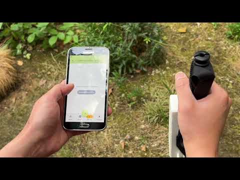
Screens from the finished Flutter build
To download the latest version of the application, navigate to the Releases tab and download the latest release.
Once the device has been assembled and the mobile application installed on your Android smartphone, follow these steps to prepare the device for use:
- Thread the velcro strap through the slots in the bracket at the back of the enclosure. Use these to securely attach the TerRanger device to your hiking stick
- Switch on TerRanger by flipping the toggle switch at the top of the enclosure and wait for a few seconds for the startup routine to complete
- Pair the device by navigating to the
Devicesscreen in the mobile application and pressing theConnect to devicebutton. - Once done, use the red-orange centre button in the middle of the bottom app bar to create a new hike and start collecting data
This section is intended for advanced makers to provide further details on the TerRanger system and how these can be modified.
The following key libraries were used in the Arduino code:
| Library | Purpose |
|---|---|
| vector | Used for Gyroscopic compensation |
| Wire | Required for I2C communication between the LiDAR sensors and the MCU |
| SparkFun_VL53L5CX_Library | Required to interface with the firmware for the VL53L5CX |
| ArduinoBLE | Used to set a device name and create a BLE characteristic that the data from the sensors can be written to |
| Arduino_LSM9DS1 | To interface with the LSM9DS1 IMU, used for Gyroscopic compensation |

Two VL53L5CX sensors attached to the circuit
The VL53L5CX sensors can be tuned to change their sampling frequency, distance array size and ranging mode, which will have effects on device performance. This can be done by calling the appropriate functions from the imported Sparkfun library in the main Arduino code, for example:
| Function | Use |
|---|---|
SparkFun_VL53L5CX.setResolution() |
To change distance array size between 4x4 and 8x8 |
SparkFun_VL53L5CX.setRangingMode() |
To set ranging mode. It is possible to select either continuous or autonomous. Continuous uses more power but is more frequent |
SparkFun_VL53L5CX..setRangingFrequency() |
To set ranging frequency in continous mode. This has been set to the maximum of 60Hz in the code, to minimize lag time |
For more information, see the Sparkfun VL53L5CX library GitHub repo and VL53L5CX datasheet and manual under External Links)
The walking stick could be oriented in a direction that is not orthogonal to the ground plane when a sample is taken. Therefore the vector library was used, and the functions calculatePitch and calculateYaw make use of this and the acceleration to pitch & yaw forumla to convert the accelerometer readings to pitch and yaw angles in degrees. These angles are transmitted to the mobile application via Bluetooth.
The device connects to the mobile application via Bluetooth Low Energy, using the Arduino BLE library. The buffer size (for transmitting data) has been set up dynamically using variables to ensure it will change should you choose to set the VL53L5CX to the 8x8 resolution (it is set to 4x4 by default and in the code). Note that this may also require changes to the peripheral BLE device code in the mobile application as it is currently configured to receive the appropriate number of btyes for the 4x4 resolution, not the 8x8.
If you elect to use the gesture recognition version of the Arduino code in Arduino/DistanceArray_ai/, you will find that it uses a TinyML or Edge AI model to power the gesture recognition functionality. The model embedded in the code as a library is a Convolutional Neural Network (CNN), that has been trained on accelerometer data from performing the gesture of double tapping the hiking stick on the ground.

Model architecture of the CNN used for gesture recognition in the DistanceArray_ai.ino file
Other architectures tested included a Recurrent Neural Network (using Long Short Term Memory layers) and a hybrid model with both LSTM and Convolutional layers. The CNN model outperformed the other two architectures by far.

Comparison of performance across different model architectures
Using Edge Impulse, it is possible to clone the project and train it on your own data or make further adjustments to the model. To visit the Edge Impulse project page, see External Links)
The key libraries that have been used in the code are:
| Library | Purpose |
|---|---|
| flutter_reactive_ble | For establishing the Bluetooth Low Energy connection to the device |
| permission_handler | For handling location and Bluetooth permissions |
| provider | To provide app state management |
| sqflite | To persist data in the background in the form of a SQL database |
| flutter_map & flutter_map_location_marker | To display a map widget |
| latlong2 & geolocator | To get the position of the user when a sample is taken |
| fl_chart, vector_math & ditredi | To manipulate and visualize the data from the sensors |
| share_plus | To provide backup functionality for the local SQL database where the data is stored |
If you wish to develop the mobile application further, first clone this entire repository with:
git clone https://github.com/ethmacc/CASA0022_TerRanger/After which, run the following command to fix and issues in the code and install dependencies (using the pubspec.yaml file in application root folder):
flutter clean

flutter pub get
To run the application in a connected Android Device or Emulator, use:
flutter runThe application can be built into and apk and installed using the following commands:
flutter build apk
flutter install
Note that if you want to push an upgrade to an existing version of the application on your Android device without overwriting the existing data collected, you should use:
adb install -r "smarthiking_app\build\app\outputs\apk\release\app-release.apk"instead of flutter install
If you wish to load data from the 3 hikes that were conducted during the course of this project, find them in the folder Data/database_backups/ and load them into your app by using the load backup function on the backups screen.
The distance array (from the VL53L5CX sensors) to point-cloud algorithm is based on scaling a list of vectors that point to each of the grid points in the sensor's field of view. This was tested and visualised initially in the Python notebooks /Data/byte_decoder.ipynb and /Data/byte_decoder_4x4.ipynb, which can also be used for further development.

The vector list visualised as a vector field using plotly in the Python notebook
The vector list has been copied and hardcoded into smarthiking_app/lib/screens/sample_detail.dart and is used in the function
List<List> parseAndScalePts(String rawData) {...}to generate the point cloud from the distance array received from the sensors.
The erosion estimation algorthim is based on the Cross-Section Analysis (CSA) method and formula as described in Olive and Marion (2009):

Diagram illustraing the CSA method, taken from Olive and Marion (2009)
This is implemented in smarthiking_app/lib/screens/sample_detail.dart in the function:
double calcErosion (List<List> sectionLists) {...}A PCB design was developed towards the end of the project, but this was not manufactured or tested. It can be found in Models/2D. A future version of the project might involve miniaturising the device further, taking and advantage of the reduced size of the electronics with a dedicated PCB and surface mount-components.


PCB design schematic (left) and 3D model (right)
It may also be possible to upgrade the sensors, which during testing were found to be less accurate than desired. The VL53L8CX, an improved model that is more able to cope with environmental factors such as high ambient light, is just starting to become more widely available.
Lastly, it would be an interesting exercise to try adapting the device to another use case, such as surveying for potholes. Pothole damage repair costs the UK approximately £143.5 million annually (Asphalt Industry Alliance, 2024).
https://github.com/sparkfun/SparkFun_VL53L5CX_Arduino_Library
https://www.st.com/resource/en/datasheet/vl53l5cx.pdf
https://studio.edgeimpulse.com/public/732758/live
Asphalt Industry Alliance. (2024). Annual Local Authority Road Maintenance Survey Report. 2024.
Olive, N. D. and Marion, J. L. (2009). ‘The influence of use-related, environmental, and managerial factors on soil loss from recreational trails’. Journal of Environmental Management, 90 (3), pp. 1483–1493. doi: 10.1016/j.jenvman.2008.10.004.
Makadiya, K (2024). Flutter Pull to Refresh: How to Implement, Customize, and Handle Errors. Dhiwise.com. Available at: https://www.dhiwise.com/post/flutter-pull-to-refresh-how-to-implement-customize (Accessed 20 Aug. 2025).
Lee, S. (2024). Safely Backing Up Sqlflite in Flutter. Medium. Available at: https://medium.com/@soojlee0701/safely-backing-up-sqlflite-in-flutter-120718588dd5 (Accessed 20 Aug. 2025).
Nitesh (2021). Flutter polyline distance with google_maps_flutter plugin. Stack Overflow. Available at: https://stackoverflow.com/questions/66181115/flutter-polyline-distance-with-google-maps-flutter-plugin (Accessed 21 Aug. 2025).
VitLit (2019). Center poly line google maps plugin flutter fit to screen google map. Stack Overflow. Available at: https://stackoverflow.com/questions/57986855/center-poly-line-google-maps-plugin-flutter-fit-to-screen-google-map (Accessed 21 Aug. 2025).
If you have any suggestions or would like to contribute to this project, please submit a pull request and/or contact me using my social links on my profile