Project web page [https://sites.google.com/site/eyalabraham/nixie-tube-clock]
- Hour and minute display
- Date display
- LED multi function indicator: seconds or blink rate change when errors
- Self adjusting time
- NTP based
- (not implemented) Visible indication when no connection to time source
- (not implemented) Default time and time keeping when no connection to time source
- Intensity control and dimming of tubes based LDR light sensor
- Watchdog communication protection between Raspberry Pi and AVR controller
- Nixie protection; ‘slot machine’ effect
- Clock tube display on/off (High Voltage on/off) by hour of the day
- High Voltage shut off via logic control
- SSH for management
- XML configuration
- (not implemented) Default time keeping when no connection
- (not implemented) NTP setup; source, time zone
- Default time format as 24 and 12 hour format (no AM PM indicator)
- ‘Slot machine’ effect configuration
- Clock on/off periods such as time of day; e.g. midnight to 7am
- Date display configuration
- NTP
- AVRdude for AVR in-circuit programming
- Python
- Time keeping with NTP service
- Read ambient light through AVR
- Control display and dimming through AVR
- Clock functions: 'slot machine' effects, time format ...
- C code for controller
- Nixie Tube digit multiplexing and PWM for dimming control
- SPI communication with RPi
- ADC sensing of ambient light with photo-resistor
Nixie Tube multiplex timing Achieve the effect of digit multiplexing and intensity control by varying the 'on' duration of a digit.
        +-----------+   +--- ...
        |           |   |
        |           |   |
        |           |   |
     ---+           +---+
      Tb   Ton/Toff   Tb

     ---^---------------^----- digit multiplex interval
           Tdigit

      Total multiplex cycle:    20mSec, total of four (4) digits
      Tdigit:                   5mSec Single digit time slot
      Tb:                       ~200uSec Blanking period
      Ton:                      range 0 to (Tdigit - Tb) Controlled by intensity setting
      Toff:                     Tdigit - Ton
SPI Command interface
| Command byte | Response | Second transmit byte | Response |
|---|---|---|---|
| 1 | dummy | Minutes digit | Current Minutes digit |
| 2 | dummy | 10s minutes digit | Current 10s minutes digit |
| 3 | dummy | Hours digit digit | Current Hours digit digit |
| 4 | dummy | 10s hours digit | Current 10s hours digit |
| 5 | dummy | Brightness 0 to 10 | dummy |
| 6 | dummy | dummy | Get light sensor 0 to 255 |
| 7 | dummy | dummy | Code rev in 2 nibbles |
| 85 | dummy | dummy | 170 |
Commands 1 through 4 are used to send new digits to be displayed on the Nixie tubes. A value of 0 to 9 displays digits 0 to 9, a value greater than 9 blanks a digit. The response to the second byte is the digit that was displayed and replace by the one just sent. This is used to produce some effects such as digit shifting.
Brightness command with value 0 turns off all tunes by turning off high voltage, values 1 through 10 control the brightness from low to high.
The notation 'dummy' denotes a dummy byte of 0xff that is sent or received but ignored.
Command number 85 (0x55) is a keep alive and check for response 170 (0xAA). This command is sent periodically: if there is no response from the AVR, the RPi will issue a reset on GPIO8, if it is not received by the AVR, the AVR will blank the display and fast-flash the seconds LED.
Follow [https://www.raspberrypi.org/forums/viewtopic.php?t=200385] to remove the fake hardware clock and then [https://www.raspberrypi.org/forums/viewtopic.php?t=178763] to setup NTP with systemd service timedatectl
Top resources
- High voltage circuit, power supply and calculations [https://threeneurons.wordpress.com/nixie-power-supply/]
- Nixie tube power switching and multiplexing [http://betawolf.nl/electronics/projects/6-antonius-nixie-tube-clock]
- Nixie tube Anode power switch [https://electronics.stackexchange.com/questions/331220/anode-driver-for-nixie-clock]
- Powering and multiplexing [http://www.glowbug.nl/neon/HowToDriveNixies.html]
- HV power supply schematics [https://onedrive.live.com/?id=F9DB37B8211CE831%21142&cid=F9DB37B8211CE831] Other resources
- Good general resource [http://www.electricstuff.co.uk/]
- Circuit design [http://www.mcamafia.de/nixie/ncp_en/ncp.htm]
- Circuit design and references [http://www.derivedlogic.com/Nixie%20Stuff/nixiestuff.html]
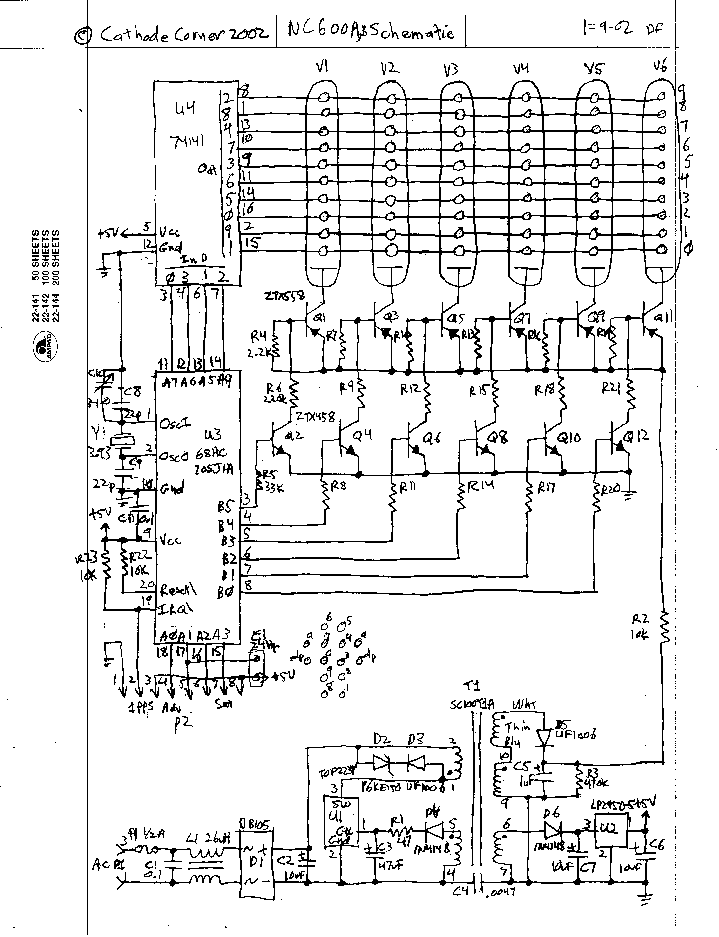
- Circuit with BCD decoder 74141 [http://www.cathodecorner.com/nc600ab.gif]
- 7441/41A/141 drivers [http://www.tube-tester.com/sites/nixie/74141-NDT/74141-NDT.htm]
Implemented design from [https://threeneurons.wordpress.com/nixie-power-supply/]. Power measurements yielded ~80% efficiency at 200VDC with a load of 10.8mA
- "Blue dot" issue [https://groups.io/g/neonixie-l/topic/in_18_strange_blue_glow_at/1048445?p=,,,20,0,0,0::recentpostdate%2Fsticky,0,,20,0,160,1048445]
- towards bottom of page: [https://threeneurons.wordpress.com/nixie-power-supply/]
- Collection of Nixie tube information [http://www.tube-tester.com/sites/nixie/nixie-tubes.htm]
- All Spectrum electronics [http://www.allspectrum.com/store/nixie-tubes-accessories-c-26.html]
- 74141 driver chip, $3.99 each
- IN-14, $12.00 each
Schematics located in Github repository [https://github.com/eyalabraham/schematics] under nixie-clock
- Raspberry Pi Zero W
- 4x IN-14 Nixie tube clock, with multiplexed digits
- HV power supply with MC34036
- Single 74141 or equivalent Nixie driver for cathode switching
- 4x pairs of MPSA42+MPSA92 anode switches for multiplexing and dimming (one pair per Nixie tube)
- ATmega328P
- MISO/MOSI/SCK/RST for direct programming from RPi Zero W
- MISO/MOSI/SCK/SS for bi-directional communication with RPi Zero W
- Connection to 74141 driver
- PD0..3: BCD digit code
- PD4..7: anode multiplex and dimming control
- PB6 - seconds LED control
- PB1 - High voltage enable=1/disable=0
- PB0 - timing test point
- PC5 - analog ambient light sensor
- RPi can remote/in-circuit program the ATmega
- RPi can read ADC light sensor
- RPi sends time for four digits
- RPi sends dimming control value
- ATmega controls/synchronizes multiplexing of digits and dimming
- ATmega operates on 3.3v like the RPi
- ATmega outputs buffered through 1x 74244 to drive transistors (protection and 3.3 to 5v logic level shift)
- ATmega328P code in C
- RPi code in Python, with SPI interfacing and single bit GPIO controls; one for Reset, one (automatic) for SPI.
- Provide pins for RPi UART console connections (backup for WiFi failure)
- RPi and AVR will exchange keep-alive messages every 10sec, if RPi fails to communicate with AVR it will issue a reset through GPIO8 if AVR fails to communicate with RPi it will blank the Nixie Tubes and fast-flash the seconds LED
There are several choices for a Python GPIO library for the Raspberry Pi. These include GPIO.ZERO, RPi.GPIO, spidev based library and possibly more. This project uses the bcm2835 'C' library and the matching Python bindings. The bcm2835 library is actively updated, and supports all GPIO options of the Raspberry Pi, including SPI, I2C, GPIO, PWM etc. The library is a compiled 'C' library, but with the Python bindings it provides full functionality for both C and Python without any need for kernel drivers. The Python binding is not up to date with the bcm2835, but is sufficiently easy to update.
- avr-nixie-ctrl.c AVR controller code
- bcm2835-python-lib setup steps for bcm2835 GPIO library and Python bindings
- RPi-GPIO-avrdude setup steps for AVRdude for in-circuit programming of AVR from RPi
- spi-test.py test program for SPI
- spi-dim-command.py test dim/brightness command by cycling through values
- spi-get-light-sensor.py read light sensor (LDR) value from AVR
- spi-running-watch-dog.py send periodic watch dog command to AVR and test response
- spi-sense-and-dim.py read light sensor value from AVR and send appropriate dim/brightness command with digit data
- nixie_clock.py main Nixie clock driver program
- clock.py time-keeping and display module
- configuration.py clock configuration and XML parsing module
- dispatcher.py time-based function dispatcher class module
- clock.xml configuration file
- startup.sh A shell script used to auto start the clock app in Raspberry Pi. Link through crontab
- README.md this file