A robot that sketches any image supplied to using a combination of Image processing, Fuzzy logic and old-school coding. Sketch-Bot The Idea A polar coordinate robot that draws any image supplied to it on a canvas using a fuzzy logic model trained in MATLAB and actuated using a combination of MATLAB and Arduino IDE. The robot was built using parts salvaged from household items and LEGO NXT motors. The Approach The project was divided into 3 following stages
- Mechanical Design
- Software
- Execution
Mechanical Design The choice of actuators for the Sketch-bot were Lego Mindstorms robots, these were selected especially for the high torque output and ease of programming and using without the requirement of additional motor drivers or encoders. However, the weight and form of the motors proved to be a challenge when implementing the design. Most of the structure of the robot was built using salvaged components from household items such as a marble used for a castor wheel. The following are the salient features of the design and description of the physical structure of the Robot.
-
The Sketch-bot is a 2.5 DOF robot, with 2 rotating links in the XY plane. The 3rd motor would only act as a mechanism to lift and lower the marker drawing the image.
-
The NXT controller acted as a counterweight to balance the weight of the robot and additional weights were implemented to stabilize the robot at extremities.
-
The 2 revolute links were 13.8cm and 14.2 cm, with a rotational range of pi/4 and pi respectively
-
The following is the visual representation of the workspace of the robot
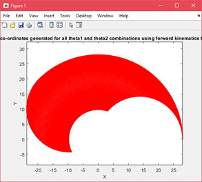
-
The following is the task space representation of the Sketch-bot
Software The software for the robot was again divided into 3 major stages given below:
- GUI - The user interface to import the image and then use it to process it
- Image processing
- Inverse Kinematics
Although listed in order, the above stages were not developed in the same order. GUI (MATLAB GUIDE) The GUI was completely developed using MATLAB GUIDE and the image processing toolbox to make certain edits to the image before sending for further processing. The following is a screenshot of the design and is elaborated in detail later.
Features of the GUI
- Import any image using the windows explorer
- Rescale the image if the resolution is too high, this is done because the resolution of the robot is limited because of the limitation of the motor resolution
- Once scale is set, you can change the RGB values individually using a slider to adjust the image output as required.
- Reset, Exit and Go button available to proceed with the image
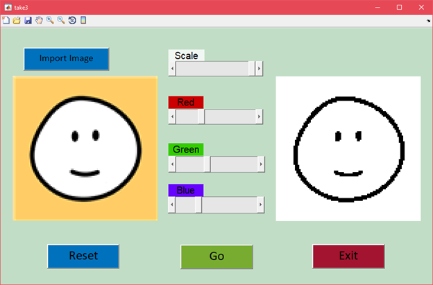
Image Processing All the image processing is done using the Image Processing Toolbox (IPT) available in MATLAB.
- Since we can only print with 1 color, we convert the image into a black and white image. To do so the user can adjust the slider as shown above to get the required output from the image.
a. The following is the snippet of code used to get the required output
b. 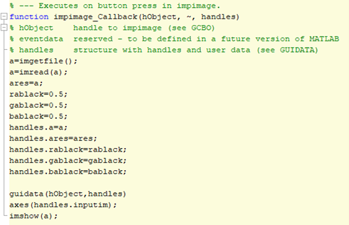
- Once we have the required output image, we hit the ‘Go’ button takes us to the next step.
- We first calculate the no. of rows and columns of the image after scaling and store the values
- Then we invert the image again to obtain the negative of our required image this is done for us to scan the image and find connected areas in the image easily
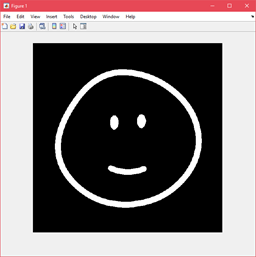
- We use the bwconncomp() function in the IPT to get a structure with the coordinates of the different “blocks” in the image.
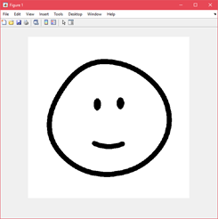
- A block in this context is defined as a set of white points that are connected or adjacent to each other. For this example, the Smile is 1 block, and the two eyes are 2 separate blocks. We have a total of 4 blocks in this image.
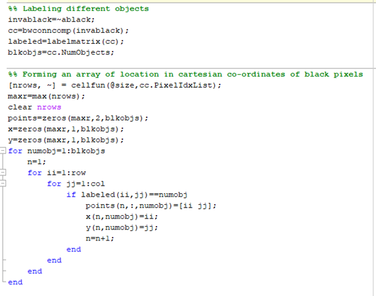
- We also label each of the blocks with a specific number to help us differentiate the blocks and assign the order in which we must draw them using the labelmatrix() function.
- Now, we extract the coordinates of each of the pixel of a particular block in the cartesian coordinates but since the pixels are found using raster scanning (from left to right) the points are unorganized and will lead to scribbles on the paper as the robot will move from left to right to go from one position to the other.
- This is solved using a separate script to order the points which we will talk about in detail later.
- We convert the same into polar coordinates and store them to use for the inverse kinematics
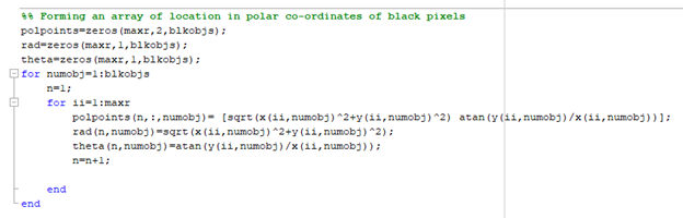
We store the polar coordinates (theta & polpoints) for inverse kinematics. Inverse Kinematics To do the Inverse Kinematics we employ a neural network trained on the fuzzy logic algorithm.
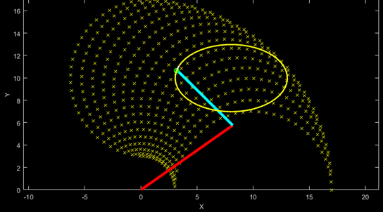
- To train the model we first create a forward kinematics model using trigonometry. X = l1 * cos(THETA1) + l2 * cos(THETA1 + THETA2); % compute x coordinates Y = l1 * sin(THETA1) + l2 * sin(THETA1 + THETA2); % compute y coordinates where l1 and l2 are length of the links,
- We create an array of Theta1 and Theta2 positions to encompass all the positions that the robot can move to.
- Now we create the respective data sets and start our training set using the anfis() command, to train 2 models for theta1 and theta2.

- Now to test our trained model we supply the trained model with a random set of positions and plot the outputs, we also supply the same data to our mathematical model and compare the outputs with each other.
- Once the model is trained, we don’t have to retrain it, instead we can send the polar coordinates (theta and polpoints) to the model and it will give us Theta1 and Theta2 for the positions of link 1 and link 2 respectively.
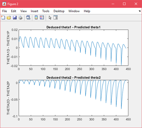
- You can see from the above image the error theta 2 is of a magnitude higher than theta1, this is because the error compounds for theta2, there is also a limitation of the resolution of the training data and the resolution of the robot.
- We store the trained model as theta1.fis and theta2.fis respectively to use later.
Execution