
motorroller is an easy to use open hardware open software stepper motor controller using Raspberry Pi. Depending on which driver you use, you can control 5 phase or 2 phase stepper motors. In this current configuration, it can control up to 4 motors. Also supported are the readout of linear potentiometers.
Please download the latest version of Raspberry Pi OS Lite. Newest versions require setting up username / password already in the imager tool. You can also enable SSH from there.
Then you can expand file system using the script raspi-config and also enable SPI.
Install some useful packages:
sudo apt udpate
sudo apt install -y screen mc tree git python3-pip emacs-nox htop sshfs
Then install python packages. You may need to provide the command line arg --break-system-packages depending on your system, but be careful with that:
pip3 install --break-system-packages RPi.GPIO spidev loguru
Clone and install the repository:
cd git
git clone https://github.com/xaratustrah/motorroller
cd motorroller
pip3 install --break-system-packages -r requirements.txt
The recommended usage is calling the script directly:
python3 -m motorrollerIt is also possible to install motorroller in the environment, but for this internet connection might be necessary:
pip3 install --break-system-packages .For uninstalling both you can type:
pip3 uninstall --break-system-packages motorrollermotorroller can be run in two different modes (the third client/server mode has not been implemented at this stage). It accepts commands in interactive and command line mode. During movement, pressing ctrl-C will stop the movement and exit gracefully.
NOTE: during any operation, in case of crash due to any reasons, make sure to re-run the code and close down properly, in order to make sure that system is gracefully shut down. This is specially important because of the magnetic break of the motors. The code makes sure that they are gently released after each operation. In case of an unexpected crash it might happen that this gentle close down is not accomplished. So by re-running the code and gently closing again, this will be guaranteed.
this is the default mode. There will be an input prompt for entering commands. Just run:
python3 -m motorrollerThe readline history is activated for convenience. You can revisit your older commands by pressing arrow up.
Use one or several commands directly in the command prompt:
python3 -m motorroller --command 0i200 0o200Moves motor 0 in and out for 200 steps. Moving motors inside and outside is always in number of steps, but the read out will print out the position values in mm.
Format is XYZ, where X is one of the following:
0 --> Motor 0
1 --> Motor
2 --> Motor 2
3 --> Motor 3

7 --> Both motors 0 and 1
8 --> Both motors 2 and 3

9 --> Read out potentiometers only, the other two positions will be ignored

Y is the direction either I for in or O for out (case insensitive)

Z is the number of steps (int)
For example 0i200 means move motor 0 inside 200 steps.
Special case of command 9:
Command 9 is just a reader, which means it does not matter what arguments are given, it will always read out the position potentiometers. So in the case of command 9, the only significant value is the number 9 itself, meaning that all other combinations are ignored.
For example the command 9i0 is the same as 9o56879 and so on.
NOTE: all commands are case insensitive, i.e. iand I are equal, same applies to oand O.
Following features work in combination with all above mentioned operation modes:
A logger file name can be provided in order to put actions and readout information together with a time stamp in a log file. You activate the logger by using the --log switch:
python3 -m motorroller --log ./logfile.txtWorking with a calibration file insures a safer operation. In the calibration file, which is TOML format limits can be set for every motor. You can provide the name of the calibration file as a command line argument:
python3 -m motorroller --log ./logfile.txt --cal clibration.tomlThis works for all modes of operation. Here is the structure of the calibration file, with example values:
# Configuration and calibration file for Motorroller

[general]
minimum_delay = 0.002 # this slows down the movement. recommended value: 0.002

# calibration point format [mm, ADC value]

[mot0]
limit_outside = 30
limit_inside = 70
cal_points = [[90, 869], [10, 3049]]

[mot1]
limit_outside = 30
limit_inside = 70
cal_points = [[90, 857], [10, 3047]]

[mot2]
limit_outside = 30
limit_inside = 70
cal_points = [[90, 831], [10, 3011]]

[mot3]
limit_outside = 30
limit_inside = 70
cal_points = [[90, 877], [10, 3039]]
NOTE: Calibration point format is [mm, ADC value]. For calibration points, within each pair, please use either floats or integers, TOML format does not allow mixing. As you know the ADC values are always integers, but position values can be floats. If you choose to have a position value that is a float, then you might need to indicate the ADC value also as a float, with ".0" at the end.
For example allowed values: [90, 831] or something like [90.5, 831.0] but not allowed: [90.5, 831]
NOTE: Please note that in the current hardware configuration, as motors move inside:
- values in mm increase
- ADC values decrease
- Motor rotation direction would correspond to CCW
This version of motorroller does not use hardware or software PWM, but instead, for increase of accuracy, it uses exact number of steps. This way, you can keep track of the motor motions for more scalability and reproducibility.
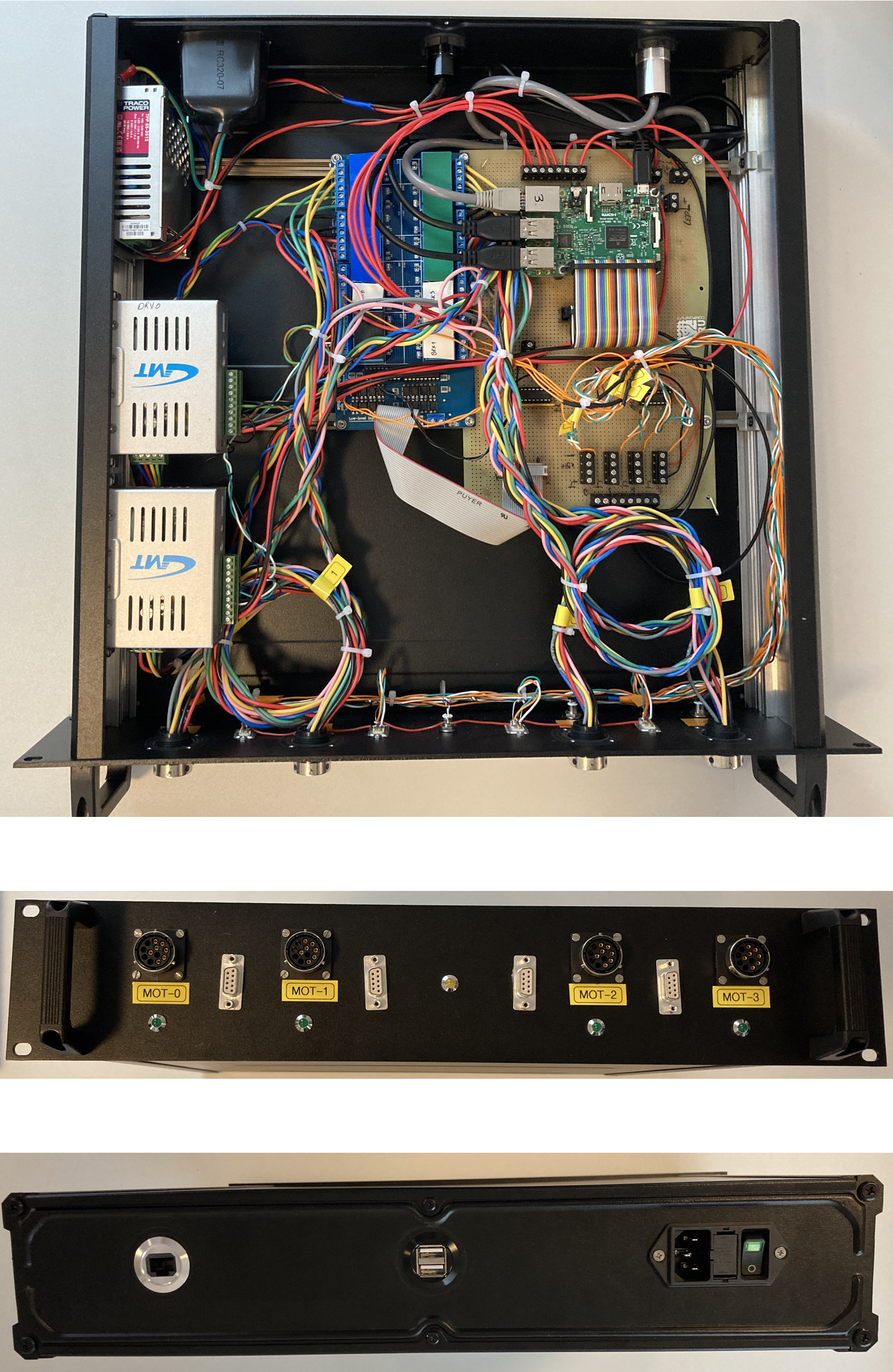
The schematics has been creating using KiCAD. The schematics file is included in the project. A PDF version of the schematics (connection plan) can be found here. Needed parts are listed also in an spread sheet document here.
This is the connection table for the 9 pin D-SUB connector:
| Pin # | Signal |
|---|---|
| 1 | End switch outside limit |
| 2 | N. C. |
| 3 | End switch GND |
| 4 | End switch inside limit |
| 5 | N. C. |
| 6 | Poti GND |
| 7 | Poti runner |
| 8 | Poti PWR |
| 9 | N. C. |
This is the connection table for round motor connector:
| Pin | Signal |
|---|---|
| A | Blue |
| B | Green |
| C | Red |
| D | Black |
| E | Orange |
| F | N. C. |
| G | N. C. |
| H | N. C. |
| J | N. C. |
| K | N. C. |
| L | Break PWR |
| M | Break GND |
-
Please note that the driver has direct opto-coupler inputs, whereas the relay board has opto-couplers that are already pulled up to 5V on one side.
-
For crimping the wires, please note that for the crimp tool you need to set level 8 for 0.75mm2 which are the motor cables, and level 5 for 0.14mm2 cables, which are the end switch and potentiometer cables.
Although end switches are connected in the hardware, please be aware that in the current version the end switches are NOT implemented. There is however a "soft" end switch that is implemented, whose ranges are set in the TOML file.
For example: while the full range of motor movements is 0mm to 100 mm, it is possible to set the limits to 30mm to 70mm.
The software based end switch will not allow any further movement when the motor has entered the limit zone. But it still allows moving past the limit when motor enters from an allowed zone.
For example: if the limit is set to 70mm, and the motor is currently at 65mm, then moving the motors by 10mm will move them past the 70mm limit to 75mm. Issuing any further command in that direction will be caught by the software end switch.
For this reason it is important to always move the motors in a series of SMALL movements and always keep an eye on the current position readout on the display.
IMPORTANT: please always move motors in smaller number of steps:
For example moving motor 0 inwards for 1000 steps: 0i1000
Here are some suggestions for an upgrade. In case a PCB is created for the project, it is recommended that the following be considered:
- Use SPI based IO-expander MCP23S08 in order to read the status of the end switches. This one would share the same SCLK, MOSI and MISO lines with the MCP2308 but would need its own chip select signal. This would be then connected to pin 26 of the Raspberry Pi header.
A hardware platform has been recently developed that can be used for future versions of motorroller and can be found on this repository. Please also have a look at another similar project called daedalus.
In order to have the analog signals of the potentiometers and the digital signals of the end switches, one should use the 10-pin header, and connect via flat cable to 9-pin D-SUB connector to the front plate. Please notice, that the 10-pin connector has a different counting direction if connected to flat-cable D-SUB connectors!
- Change relay order
For the next revision, the relay order for the BRK signals could be made more symmetric around the relay board connector:
| Pin # | Rev 0 | Rev 0 connection | Future connection |
|---|---|---|---|
| 1 | 5V | 5V | 5V |
| 2 | 5V | 5V | 5V |
| 3 | REL1 | motor_select | motor_select |
| 4 | REL2 | motor_select | motor_select |
| 5 | REL3 | motor_select | motor_select |
| 6 | REL4 | motor_select | motor_select |
| 7 | REL5 | motor_select | motor_select |
| 8 | REL6 | brk0 | brk0 |
| 9 | REL7 | driver_select | brk1 |
| 10 | REL8 | driver_select | driver_select |
| 11 | REL9 | brk1 | driver_select |
| 12 | REL10 | brk2 | brk3 |
| 13 | REL11 | brk3 | brk2 |
| 14 | REL12 | motor_select | motor_select |
| 15 | REL13 | motor_select | motor_select |
| 16 | REL14 | motor_select | motor_select |
| 17 | REL15 | motor_select | motor_select |
| 18 | REL16 | motor_select | motor_select |
| 19 | GND | GND | GND |
| 20 | GND | GND | GND |
- Level shifters
This is a nice to have option, just add two level shifters for the CCW and CLW signals. In principle, a level shifter can also replace the darlington array IC ULN2003A , which is a bit of an overkill for the current purpose.
Please see the file LICENSE.md for further information about how the content is licensed.
Many thanks to Robert Boywitt, Roland Fischer and Sven Schuhmacher for helping with the connection plans and correct identification of the parts, and Davide Racano for providing help with the mechanical preparation of the enclosure.