Implementation
The implementation of the simulation tool was challenging. I should cover a minimum product viable to create, load, save, update, analyze payment channel based networks, simulate stress tests, provide routing mechanisms direct and routed transactions, change simulation inputs while the simulation is loaded and displayed, Consequently, I needed an exportable format to work as an internal core to load, save and read the required parameters to display the lightning network. The selected exportable format of my preference was JSON. An object-oriented data exchange language alternative from XML that I was familiar with.
As described on the design specifications and visualized in the UML Class Diagram, the Lightning Network Simulator has an object-oriented architecture. Therefore, designing robust classes for objects creation was required.
The Channel object contains the following properties:
- ID. An Integer object type that stores an identification number. Each ID is unique and is used to find nodes along the network.
- Fee. A Double object type that stores the number of the fee imposed by the node who emits the channel.
- From. An Integer object type that stores the id from the emitter node.
- Capacity. An Integer object type that stores the maximum unit a node can send through this object.
- To. An Integer object type that stores the id from the transmitter node.
The transaction object contains the following properties:
- Payment Request. A String object type that stores an identification string when a transaction is requested.
- Created At. A Date object type that stores the date when a transaction is generated.
- Expired At. A Date object type that stores the date when a transaction is expired after being generated.
- Tokens. An Integer object type that stores the recipient amount.
The node object contains the following properties:
- Balance. An Integer object type that stores the number of units to send transactions. In the lightning network, this unit is measured in satoshis. One bitcoin is equal to 1*10000 satoshis.
- Channels. An ArrayList object of channels that store channels.
- ID. An Integer object type that stores an identification number. Each ID is unique and is used to find nodes along the network.
- Alias. A String object type that stores a custom alias for the node. The alias is used in the lightning network to customize the node.
- Inbound Capacity. An Integer object type that stores the maximum unit a node can receive through all the channels.
- Outbound Capacity. An Integer object type that stores the maximum unit a node can send through all the channels.
- Transactions. An ArrayList object of transactions that store transactions sent by the node.
The network model was composed of JSON objects and arrays. In the lightning network, nodes can send and receive transactions through channels. Therefore, in an object-oriented approach, I defined the three main objects with its characteristics, the node object, the channel object and the transaction object.
The final model for the network map was based on replicating oriented architecture described in lightning network simulator specification design. The three main object entities are written in the same format the objects are created in the program. This implementation radically improves the creation of the JSON network map with the essential information ready to read and load. The final implementation of the network model is displayed below.
Generating a lightning network required to first create a network model. A JSON file containing the information of network configuration. Replicating the same scenario as in the lightning network, where all the nodes share public information about their channels, balances, and more settings. However, transactions remain private. Thus, before creating the network model, it was necessary to design the JSON architecture to be object-oriented friendly.
There are two methods to create a Lightning Network:
- Loading a Network. Create a lightning network by loading an existing network map which meets the criteria of format (JSON) and architecture syntax (object-oriented). This method read the input from the network map and recreates the network simulation by creating the main entity objects.
- Creating a new Network. Create a lightning network by writing a new network model into a map that meets the automatically meets the criteria of format (JSON) and architecture syntax (object-oriented). This method asks two inputs for the generation of the network model. The number of nodes is the input to calculate the network size. The number of channels per node is the input to calculate the number of channels per node in the network. When creating a new network model, the channel capacities and node balances are randomly generated. Making a combined network of different individual outputs. The secret seed from the random generation of values is safely stored in the network map when the model is generated. The secret seed is used to reproduce the same values in further analysis to compare and evaluate the network topology, behaviour and results.
The network map is object-oriented friendly; this allowed me to easily create the required object to recreate the lightning network simulation.
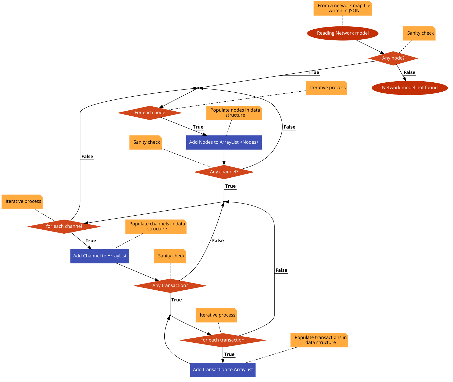
The accuracy of the reading function was challenging to achieve since it was based on for loops. As an example, the logic behind the function was:
- For each transaction of each node in the network map creates an ArrayList of transactions.
- For each channel of each node in the network map creates an ArrayList of channels.
- For each node in the network map creates an ArrayList of nodes, that at the same time each node contains its specific ArrayList of channels and Transaction.
The main complexity of the reading function was in step 3. I had to make sure that the creation of transaction, channels and node objects was procedurally in order.
for (com.carlos.lnsim.lnsim.Node node : load.getNodes()) {
    i++;
    if (New){
        width.add(i, Double.valueOf(ThreadLocalRandom.current().nextInt(2, 1500 + 1)));
        height.add(i, Double.valueOf(ThreadLocalRandom.current().nextInt(2, 780 + 1)));
    }

    Element element = doc.createElement("Node");
    element.setAttribute("ID", String.valueOf(node.getId()));
    element.setAttribute("balance", String.valueOf(node.getBalance()));

    if (node.getBalance() > 600) {
    graph.insertVertex(parent, String.valueOf(node.getId()), element, width.get(i), height.get(i), 80, 30,
    "ROUNDED;strokeColor=green;fillColor=green;fontColor=white");
    } else if (node.getBalance() >= 200 && node.getBalance() <= 599){
    graph.insertVertex(parent, String.valueOf(node.getId()), element, width.get(i), height.get(i), 80, 30,
    "ROUNDED;strokeColor=orange;fillColor=orange;fontColor=white");
    } else if (node.getBalance() >= 0 && node.getBalance() <= 199){
    graph.insertVertex(parent, String.valueOf(node.getId()), element, width.get(i), height.get(i), 80, 30,
    "ROUNDED;strokeColor=red;fillColor=red;fontColor=white");
   }
}

int j = load.getNodes().
for (Channel channel: load.
j++;
Element relation = doc.createElement("Channel");
relation.setAttribute("capacity", String.valueOf(channel.getCapacity()));

mxCell fromCell = (mxCell) ((mxGraphModel)graph.getModel()).getCell(String.valueOf(channel.getFrom()+1));
mxCell toCell = (mxCell) ((mxGraphModel)graph.getModel()).getCell(String.valueOf(channel.getTo()+1));

if (channel.getCapacity() > 80.0){
        graph.insertEdge(parent, String.valueOf(j), relation, fromCell, toCell, "ROUNDED;strokeColor=green;strokeWidth=7");
        } else if ((channel.getCapacity() >= 70.0)&& (channel.getCapacity() <= 80.0)){
        graph.insertEdge(parent, String.valueOf(j), relation, fromCell, toCell, "ROUNDED;strokeColor=green;strokeWidth=6");
        } else if ((channel.getCapacity() >= 60.0)&& (channel.getCapacity() <= 79.9)){
        graph.insertEdge(parent, String.valueOf(j), relation, fromCell, toCell, "ROUNDED;strokeColor=green;strokeWidth=5");
        } else if ((channel.getCapacity() >= 50.0)&& (channel.getCapacity() <= 69.9)){
        graph.insertEdge(parent, String.valueOf(j), relation, fromCell, toCell, "ROUNDED;strokeColor=orange;strokeWidth=4");
        } else if ((channel.getCapacity() >= 40.0)&& (channel.getCapacity() <= 59.9)){
        graph.insertEdge(parent, String.valueOf(j), relation, fromCell, toCell, "ROUNDED;strokeColor=orange;strokeWidth=3");
        } else if ((channel.getCapacity() >= 30.0)&& (channel.getCapacity() <= 49.9)){
        graph.insertEdge(parent, String.valueOf(j), relation, fromCell, toCell, "ROUNDED;strokeColor=orange;strokeWidth=2");
        } else if ((channel.getCapacity() >= 20.0)&& (channel.getCapacity() <= 39.9)){
        graph.insertEdge(parent, String.valueOf(j), relation, fromCell, toCell, "ROUNDED;strokeColor=red;strokeWidth=1");
        }
    }
}
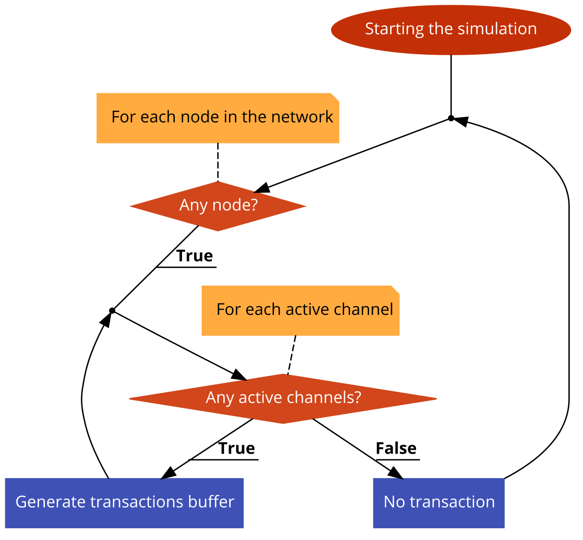
Once the simulation has been successfully loaded and displayed on top of the simulation tool, when the user clicks on the toolbar in Edit<Start the simulation start creating a transaction stress test. The implementation of this stress test simulation works in the following way. For each node in the loaded network, if it has an active channel, for each of those channels while the capacity is not equal to zero, create transaction of random recipients to random destination nodes. However, if it has congested channels or no channels at all, the transactions stress test cannot create transactions as it means this node is isolated and thus, unreachable in the network.
Transactions are stored in a transaction buffer within a class in charge of the traffic generation and the routing mechanism to find optimum paths for transactions (TrafficGenerator.java).
The simulation components should be updated constantly according to the design specification. Therefore, to not affect the global performance of the program, I needed to create a thread object entity to support asynchronous tasks. An issue appeared when the GUI was continually updating, since the tools I was using to display visual elements for the lightning network simulator were relatively old (Swing), I had to manually remove all of the UI components and add them every time I wanted the simulation tool to graphically update the network.
When transactions are loaded into a data structure from the traffic generator object, and there is no direct links found in the HashMap used to manage node paths. The routing mechanism iterate over the primary active channels from the sender nodes to fins the neighbour's nodes. Next, it checks the neighbour routes to find a path to the destination node iteratively. If any neighbour node has an active channel to the receiver node, it proceeds with the sanity checks. The sanity checks involve:
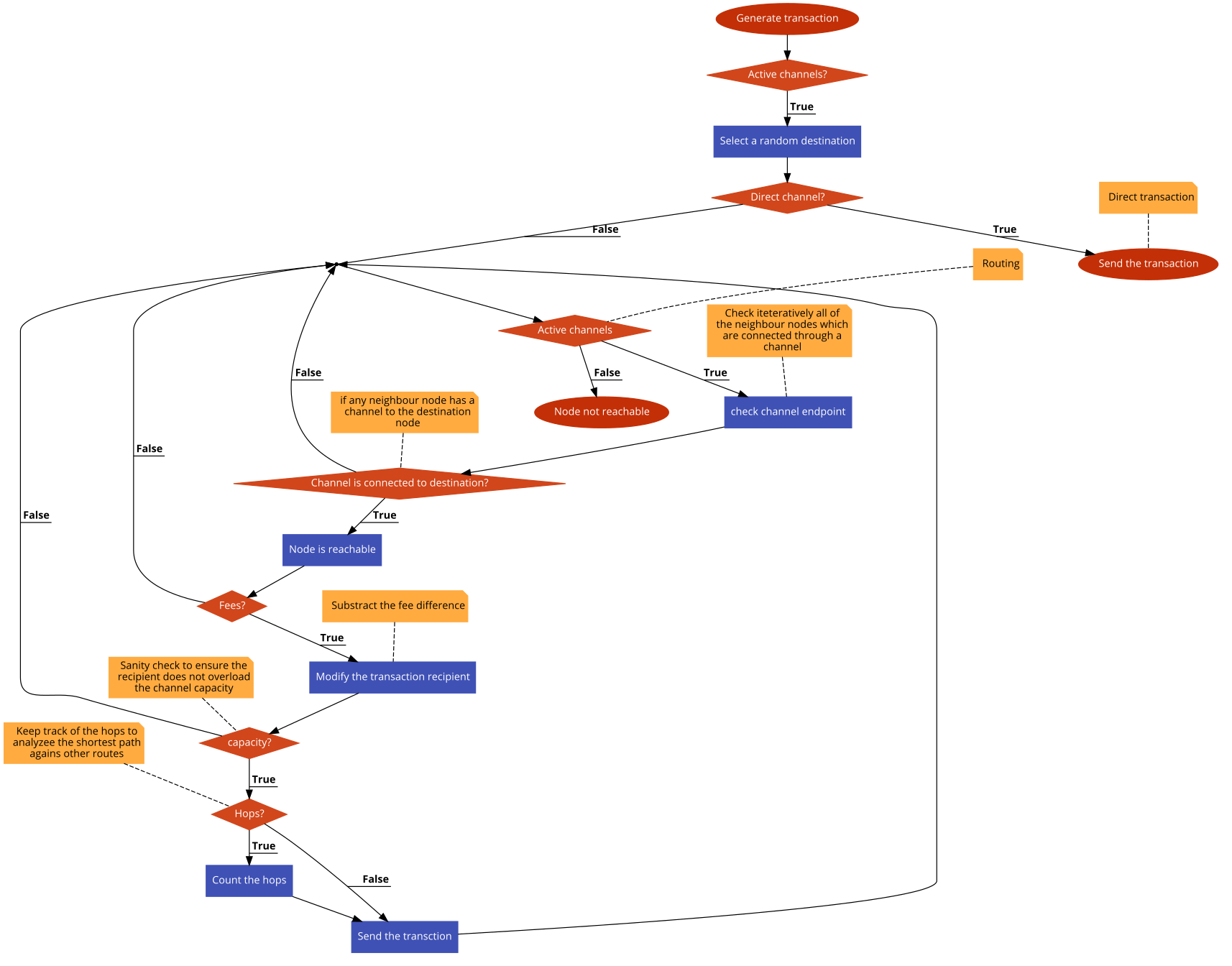
- Fees. This check serves to determine the cost of the path. Since neighbour nodes can route transactions at a cost. Every route is likely different from the other in term of cost. A convenient channel is a channel with the minimum cost possible.
- Hops. This check serves to determine the shortest path between the sender node and the receiver node. More hops involve a higher probability to increase transaction costs. A well-connected node will offer convenient routes without involving many hops.
- Capacity. This check serves to determine the availability of the path. If the transaction recipient is higher than the neighbour's channel capacity, the transaction fails, and a different routing alternative should be considered such as AMP.
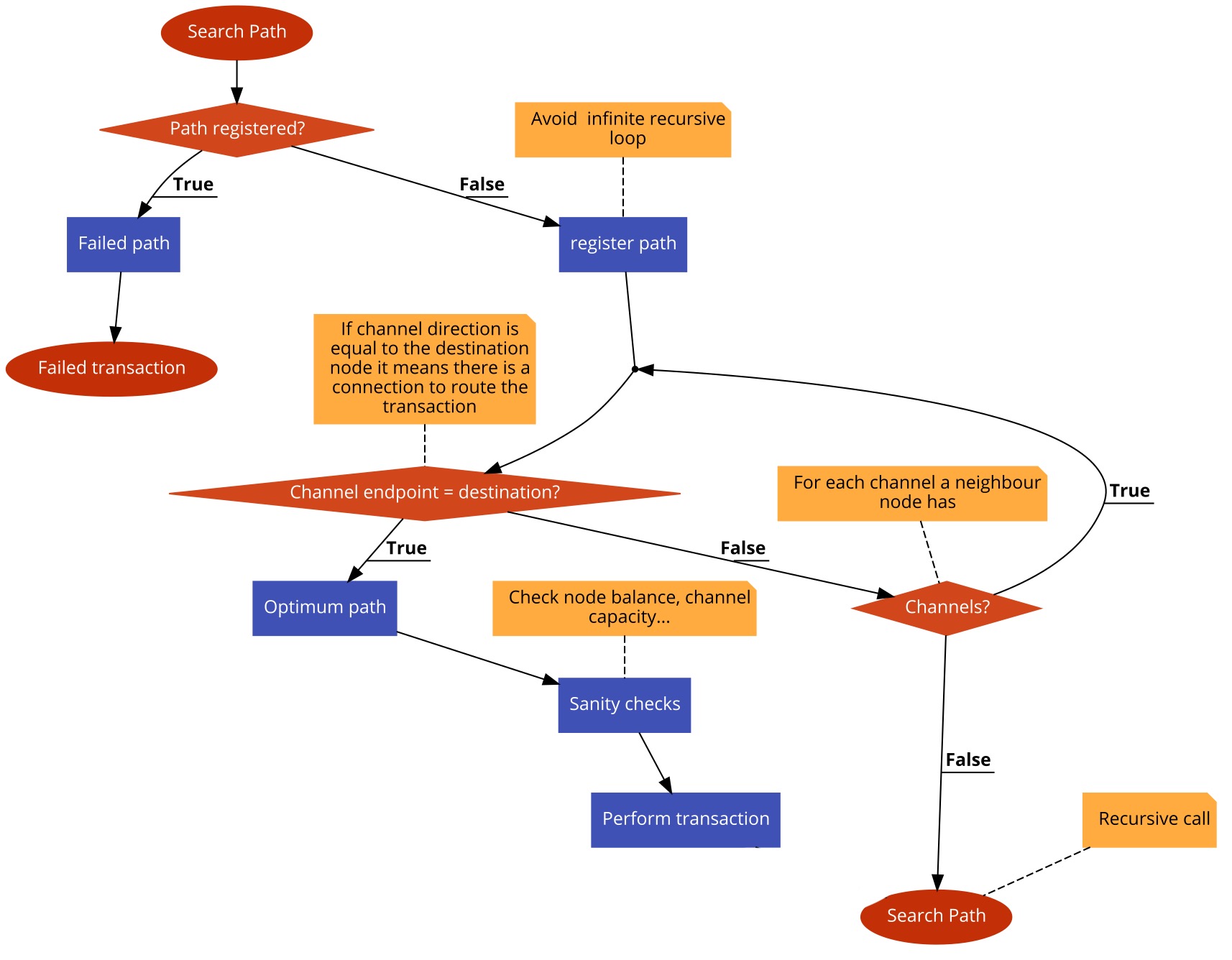
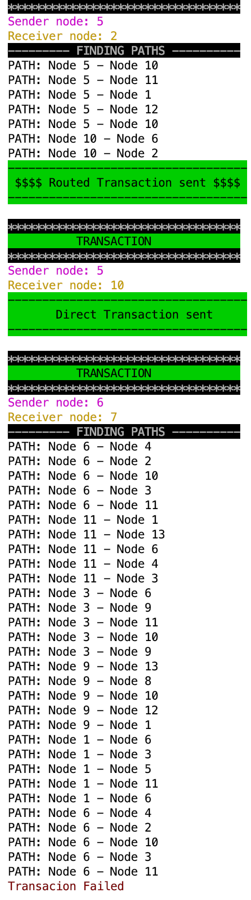
When routing transactions, the simulation tool is automatically and dynamically updated every time a transaction is successfully performed. Alternatively, details about how the transaction was routed are displayed in the terminal as part of good practice. The routing outputs were highly beneficial to understand the recursive method of how transactions are routed optimizing the first shortest path.
The routing mechanism searches every channel a neighbour has, keeping track of the last channel searched to avoid a recursive infinite loop as displayed in the visual pseudocode diagram. The routing mechanism searches was a personal implementation based on the Dijkstra's shortest path algorithm but based for the lightning network needs.
private Node searchPath(Node node, Node to, Load l, int r) {
		boolean skip = false;
		boolean ocurrence = false;
		Node temp = new Node();

		if (hops>0){
			if (checkedPaths.contains(channel)){
				skip = true;
				invalidPath = true;
				failedTransactions.add(new Transaction(node, Double.valueOf(r)));
			}else {
				// add last channel used in the list to no stop infinite recursion
				checkedPaths.add(channel);
			}
		}

		if (!invalidPath){
			if (!skip){
				// for each channel of selected node
					for (Channel c : node.getChannels()) {

						// receiver node from path route
						temp = node.findNode(node, c.getTo(), l.getNodes());
						channel = l.findChannel(channel, node.getId(), temp.getId());

						// print the path
						System.out.println("PATH: Node " + c.getFrom() + " - Node " + c.getTo());

						// receiver node equal to destination
						if (c.getTo() == to.getId()) {
							node = node.findNode(node, c.getTo(), l.getNodes());
							ocurrence = true;
							fee = c.getFee();
							break;
						}
					}
				}
			hops++;

			//recursive call
			if (!ocurrence)
				node = searchPath(temp, to, l, r);
			}

		// force the node to be the found node
		return node;
	}
The analysis tool was considerably less challenging than the simulation tool. I should cover a minimum product viable to display the simulation results, export them in a network map and view them by making the use of provided charts. Consequently, I needed to transport the results in the network map using the network data model syntax, including the random generation seed. So when the network is loaded no new random inputs are generated, and there is some consistency to proceed further with the research of the routing mechanism to find optimum paths to deliver transactions.
Delivering the management option to modify the network inputs in real-time once the simulation is loaded id being displayed was challenging but less overwhelming that completing the fitness function of routing transactions. I had to be compliant with the design specification to offer a visual distinction in the network topology by increasing or decreasing the channel with in relation to its capacities or adjusting the colour of some simulation UI components.
I implemented a very similar function from the one that draws up the network UI components when the network is loaded in the simulation tool. For all of the node balances and channel balances, I had to establish 3 different ranges to determine the high, medium or low amount. When this ranges and rules were successfully settled then I had to update all of the node balances or channel capacities in the network according to the user input. The user had a direct interaction to manage the network inputs from the toolbar, in the Edit section.
When all of the node balances or channel capacities from the network were updated, all of the simulation UI components should be interactively refreshed without affecting the location of them. When a network is displayed for the first time, all of its UI components are randomly located in a canvas range related to the screen resolution. Hence, I needed to differentiate the first when a network is displayed by making use of a boolean to switch true or false when this happens so I can make the location static to not change when the user is managing the network inputs using the simulation tool.
According to the design specifications, the exporting process of the lightning network simulation and results must be done by writing a network map which contains the network data model syntax.
Exporting the network is a feature that the simulation tool does by default when a new network is generated. When this happens the network is written by default in a JSON file named custom.json. If by any chance when the user creates a network the program would crash or the user local machine shuts down, the network is safely stored. The architecture of the lightning network simulator is designed to prevent corruption or biased simulation results in case of a crash. That is why it writes a network map before loading it on top of the simulation when a network is generated.
When the simulation results are obtained a new data object is written into the network map following the network data model syntax. This data object named results contains the simulation results structured. When the results are exported and loaded into the simulation tool. When the simulated transaction stress test event is reproduced the same outputs are gathered.
When the simulation has successfully concluded, the results are displayed to the user according to the design specification by using a sidebar in the right side of the lightning network simulator. This frame is within the main simulation frame, it uses a grid layout to composed of 0 rows and 2 columns. The first column is for the result definition and the second column is for the value.
Additionally, the simulation results can be viewed using interactive charts provided by the analysis tool through the toolbar. According to the design criteria, there are 4 different types of interactive chart visualization.
During the simulation, events such as transactions or channels congestion happen instantly. However, during the simulation, there is a constant used to analyze the simulation results. This constant is a simulated time which by default depends on the following rules:
- Open a channel - 10/20 min.
- On-chain transaction - 10/20 min.
- Off-chain transaction - Instantly.
These rules are assumptions obtained from the current average time length on-chain in the Bitcoin main network on 10/4/2019 at 21:11.