Testing
Testing the lightning network simulation tool was a key process to assert the performance, goodness and conditions of internal functions to deliver a high-quality simulation and analysis tool. The tests implemented in the lightning network simulator are:
- Unit test. Automated tests using the JUnit test framework.
- UI tests. UI tests using the JUnit test framework.
- Case tests. Manual case test using Excel sheets to replicate cases.
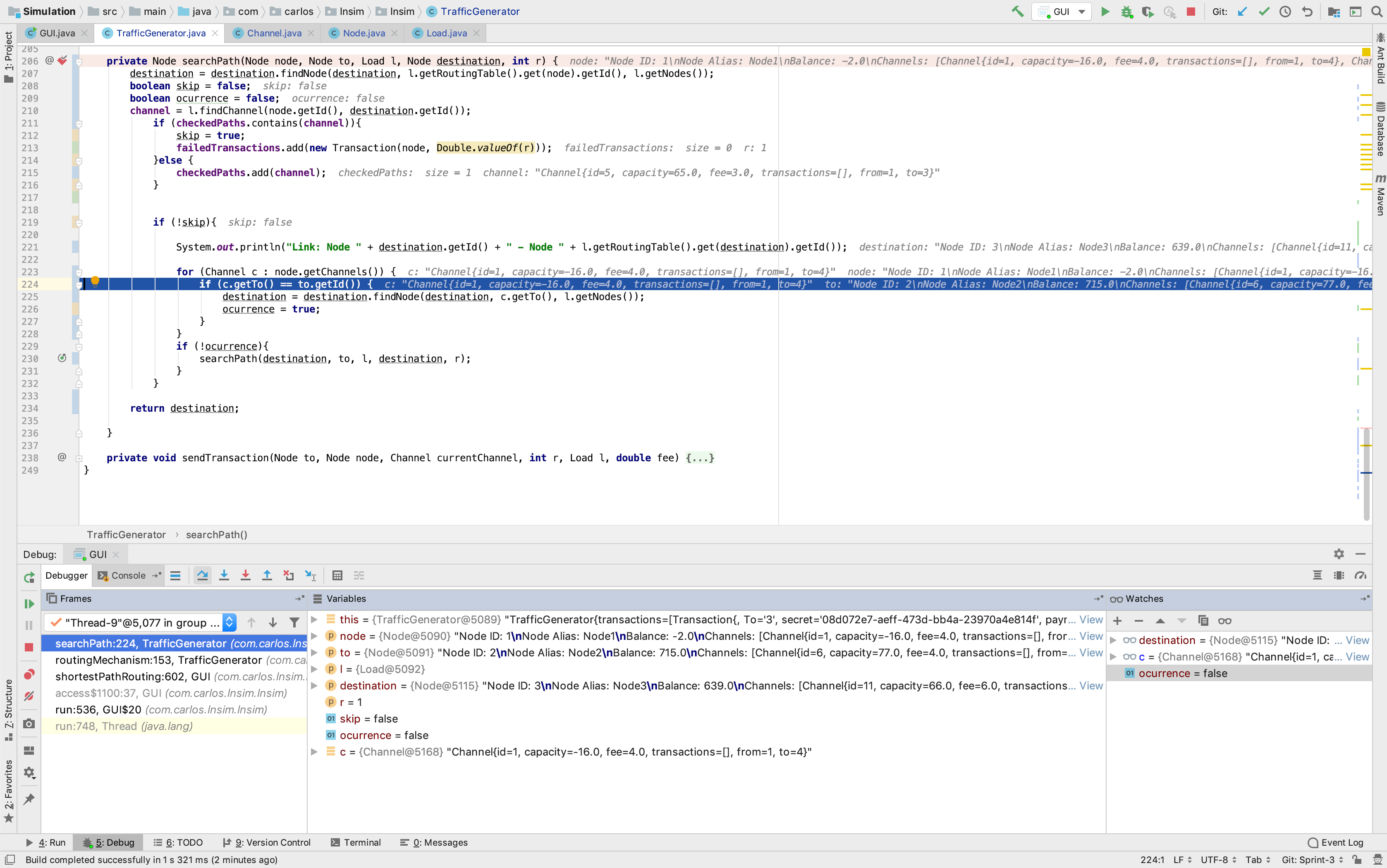
- Debugging as Manual Testing. Using the debugging tools to reproduce internal procedural cases.
Unit testing involves breaking the lightning network simulator into sections and subjecting each piece to a series of tests. The 2 subjects to test are the analysis and simulation tool.
Unit testing was fundamental to determine singular processes in the simulation tool to provide the network map, create, load and simulate a network as well as route transactions through channels.
Creating a network map involved using the correct network data model syntax to read and write simulation inputs. Thus, I implemented a unit test to assert the expected inputs when creating a network map were equal to the network map outputs once is created.
Test code is represented below:
        @Test
	public void createNetworkMap() {
		NetwrokMapGenerator network = new NetwrokMapGenerator(40, 3);
		System.out.println("Creating network map using the network data model syntax");
		network.createNetwork();
		System.out.println("Network Map created");
		assertEquals(40, network.getNodeSize());
		assertEquals(3, network.getChannelsPerNode());
	}
Loading a network required to create a network using the network map and input for the channel and node inputs. Once the network map is created an object entity to load the network into the simulation must be created. Next, the load object entity automatically loads a network if finds a network map. Therefore, asserting the expected outputs from the simulated network against the inputs used to generate the network map checks the integrity the loading functions.
Test code is represented below:
@Test
	public void LoadNetworkSimulation() {
		System.out.println("Creating network map using the network data model syntax");
		NetwrokMapGenerator network = new NetwrokMapGenerator(40, 3);
		System.out.println("Network Map created");
		network.createNetwork();
		System.out.println("Loading network map into the simulation");
		Load load = new Load();
		System.out.println("Network loaded into the simulation");
		assertEquals(40, load.getNodes().size());
		assertEquals(3*40, load.getChannels().size());
	}
Unit testing was required to determine singular processes in the analysis tool to evaluate the management of simulation inputs as well as the exporting process of the simulation results.
The management of the simulation inputs requires to create, load and display a simulated network. Next, the internal process of managing the simulations inputs is based on updating and saving the network map. Therefore, replace all of the node balances and channel capacities displayed in the simulated network for testing inputs and assert those against the expected outputs when updated.
Test code is represented below:
@Test public void ManageInputSimulations() {
		System.out.println("Creating network map using the network data model syntax");
		NetwrokMapGenerator network = new NetwrokMapGenerator(40, 3);
		System.out.println("Network Map created");
		network.createNetwork();
		System.out.println("Loading network map into the simulation");
		Load load = new Load();
		System.out.println("Network loaded into the simulation");

		System.out.println("Displaying simulation");
		GUI gui = new GUI(load);

		System.out.println("Testing balance inputs from simulation");
		gui.setBalances(3,3);
		for (Node n : load.getNodes()) {
			assertEquals(3, n.getBalance());
		}
		System.out.println("Balance inputs tested");

		System.out.println("Testing capacity inputs from simulation");
		gui.setCapacities(5,5);
		Double test = 5.0;
		for (Channel c : load.getChannels()) {
			assertEquals(test, c.getCapacity());
		}
		System.out.println("Capacity inputs tested");

	}
The exporting process is based on updating the network map. In a very similar methodology as the test for the management of the simulation inputs, the exporting process also updates the network map in compliance with the network data model syntax to write a JSON object with the simulation results.
Test code is represented below:
UI testing involves checking certain UI components are well positioned, existing or visible. This type of testing was required to check the visibility of some UI components in the lightning network simulation such as channels or nodes.
User Interface testing was fundamental to check the visibility and existence of UI components during the simulation such as vertexes to represent network nodes or edges to express the network channels during the simulation.
Displaying the network simulation requires to generate a network map and loading it on top of the simulation tool. Once loaded the test is based on checking the visibility of the simulation tool in the mainframe.
According to the design specification, the toolbar should be always visible at the top of the lightning network simulator. Checking the visibility and the options available at the toolbar is the main UI test.
User Interface testing was required to check the visibility and existence of UI components during the analysis of the simulation tool.
When the lightning network simulation has ended, a frame located at the right side of the simulation tool should exist and be visible. The simulation results are generated after a transaction stress test from network nodes until the node balances or the channel capacities reach zero.
Case testing involved a specification of the inputs, conditions, and expected results for the testing fields of the lightning network simulator. The type of testing was more slightly more complete and, hence, with a higher degree of complexity to implement and compute than the automated unit or UI tests.
An excel sheet containing the information about executing conditions, expected results and inputs were used as the test workbench to complete case tests while using the lightning network simulator.
Case testing was crucial to check in detail the complex process associated with the simulation tool such as the simulation interactivity when changes happen in the simulation process and the accuracy of the routing mechanism when the transaction stress test takes place.
This test proves the interactivity of the simulation processes when the lightning network simulation starts. Each node should behave interactively by being able to move it by a drag and drop operation or update the node balance by double-clicking the node form the simulation tool. Channel capacities should also be updated when the network is displayed by double-clicking the channel interactively.
This test proves the accuracy of the routing mechanism over the simulated network. Different network inputs have different behaviours; a simulated network where nodes are well connected, its channel capacities are low but node balances are relatively high have a different network behaviour than a simulated network where nodes are barely connected, its channel capacities and node balances are high.
The routing accuracy is key to represent the routing efficiency. This test is measured against other simulated networks with to analyze, compare and research different behaviours of the fitness function; the routing function.
Case testing was essential to examine in detail the combined processes incorporated in the analysis tool such as the visual representation of the simulation results using interactive charts for further analysis or testing the static preservation of the UI components in the simulation when the network is loaded and its inputs are replaced.
According to the design specification, representing the simulation results using interactive charts required third party services to provide this feature. The analysis tool provides three different types of interactive charts:
-
Pie charts. This type of chart is used to visualize and analyze the results of the behaviour of the channels after a network simulation. The interactive element allows the user to interact with the chart when clicking on it.
-
Linear charts. This type of chart is utilised to visualize and examine the performance outcome of the transaction after a network simulation. The interactive element allows the user to interact with the chart when clicking on it.
-
Scatter plot. This type of chart is utilised to conceive and measure the behaviour of the network after a simulation. The interactive element allows the user to interact with the chart when clicking on it.
Updating the thee simulation inputs when the network is loaded and being displayed in the simulation tool takes place statically. The first time the network is displayed, each node is located in a random location within the simulation tool. Since updating requires to refresh the UI simulation components, the initial locations are maintained statically without affecting them when refreshed.